Electromagnetic speed-adjustable motor

A technology of electromagnetic speed regulation and motor, which is applied in the direction of electric components, control electromechanical brakes, electrical components, etc., can solve the problems of inaccurate positioning and inability to stop immediately, and achieve the effects of accurate positioning, electric convenience, and short braking time

Inactive Publication Date: 2012-11-21
蔡国明
View PDF0 Cites 2 Cited by
  • Summary
  • Abstract
  • Description
  • Claims
  • Application Information

AI Technical Summary

Problems solved by technology

[0002] The traditional electromagnetic speed-regulating motor is composed of an asynchronous motor, a slip clutch, a tachogenerator, and a control device. It is convenient for speed regulation, but it cannot stop immediately. When parking, it needs to slide for a period of time, and the positioning cannot be accurate.

Method used


Image

  • Electromagnetic speed-adjustable motor

Examples


Embodiment Construction

[0008] In order to deepen the understanding of the present invention, the present invention will be further described below in conjunction with the embodiments and accompanying drawings. The embodiments are only used to explain the present invention and do not constitute a limitation to the protection scope of the present invention.

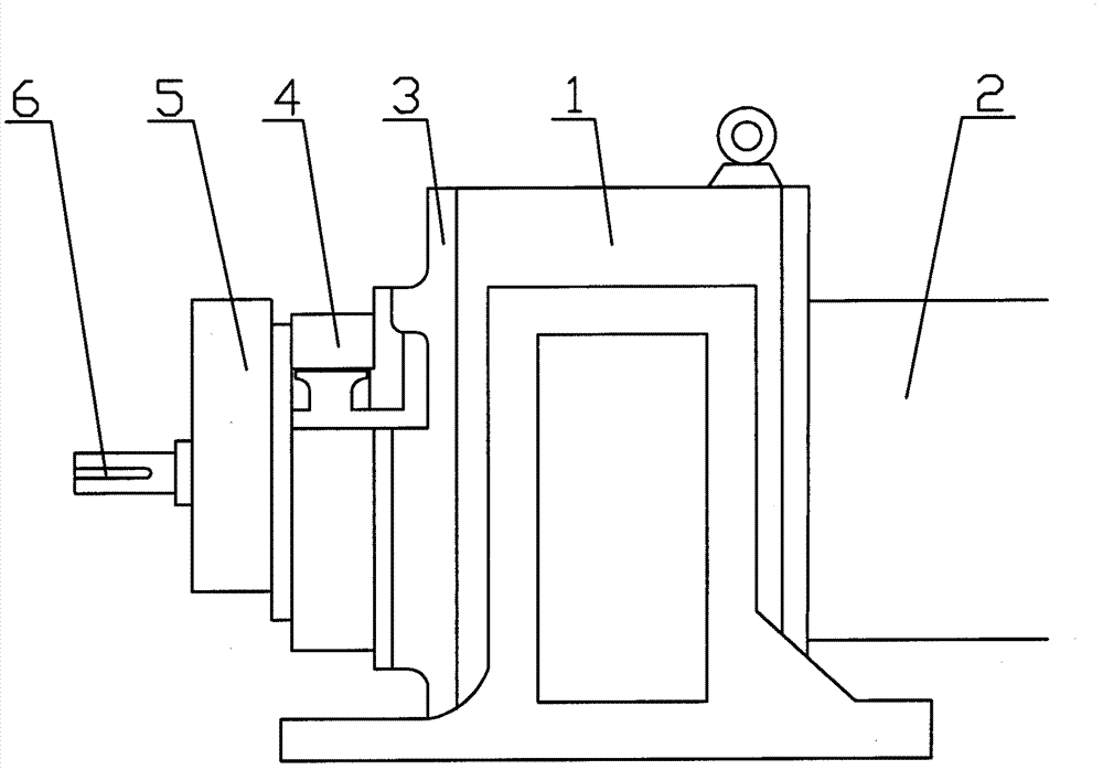
[0009] Such as figure 1 An embodiment of the electromagnetic speed-regulating motor of the present invention is shown, including a slip clutch 1, an electromagnetic speed-regulating motor 2 is provided at one end of the slip clutch 1, and an end cover 3 is set on the other end of the slip clutch 1. One side of the cover 3 is provided with a magnetic powder controller 4, and the other side of the magnetic powder controller 4 is connected with a tachogenerator 5, and the output shaft 6 at one end of the electromagnetic speed regulating motor 2 passes through the slip clutch 1, the electromagnetic speed regulating motor 2, The end cover 3, the magne...


PUM


Abstract

The invention discloses an electromagnetic speed-adjustable motor, comprising a slip clutch. An electromagnetic speed-adjustable motor is disposed on an end of the slip clutch, and an end cover is disposed on the other end of the slip clutch. A magnetic powder controller is disposed on an end of the end cover. The other end of the magnetic powder controller is provided with a speed voltage generator. An output shaft disposed on an end of the electromagnetic speed-adjustable motor passes through the slip clutch, the electromagnetic speed-adjustable motor, the end cover, the magnetic powder controller, and the speed voltage generator, and the output shaft is disposed outside the speed voltage generator. The electromagnetic speed-adjustable motor is advantaged by reasonable structure, short braking time, and accurate positioning.

Description

Technical field: [0001] The invention relates to an electromagnetic speed regulating motor. Background technique: [0002] The traditional electromagnetic speed-regulating motor is composed of an asynchronous motor, a slip clutch, a tachogenerator, and a control device. It is convenient for speed regulation, but it cannot stop immediately. When parking, it needs to slide for a period of time, and the positioning cannot be accurate. Invention content: [0003] The object of the present invention is to overcome the above disadvantages and provide an electromagnetic speed-regulating motor with reasonable structure, short braking time and accurate positioning. [0004] The purpose of the present invention is achieved through the following technical solutions: an electromagnetic speed-regulating motor, including a slip clutch, one end of the slip clutch is provided with an electromagnetic speed-regulating motor, the other end of the slip clutch is covered with an end cover, and...

Claims


Application Information

Patent Timeline
Patent Type & Authority Applications(China)
IPC IPC(8): H02K7/10H02P15/02
Inventor 蔡国明张建新唐林平陶宗跃
Owner 蔡国明
Why Eureka
Try Eureka