Electronically controlled directionally rotating single-phase self-starting permanent-magnet synchronous motor

A directional rotation, electronic control technology, applied in the direction of a single motor speed/torque control, electronic commutator, etc., can solve problems such as high noise and temperature rise

Active Publication Date: 2012-11-21
HANYU GRP CO LTD
View PDF7 Cites 18 Cited by
  • Summary
  • Abstract
  • Description
  • Claims
  • Application Information

AI Technical Summary

Problems solved by technology

Compared with the asynchronous motor used before, this motor is obviously energy-saving and material-saving, but it vibrates, makes noise and has a high temperature rise during no-load operation, so it needs to be improved

Method used


Image

  • Electronically controlled directionally rotating single-phase self-starting permanent-magnet synchronous motor
  • Electronically controlled directionally rotating single-phase self-starting permanent-magnet synchronous motor
  • Electronically controlled directionally rotating single-phase self-starting permanent-magnet synchronous motor

Examples


Embodiment Construction

[0024] The motor of the embodiment of the present invention is improved on the basis of the motor described in Embodiment 1 of the prior patent application CN201110100111.6 specification of the designer of the present invention.

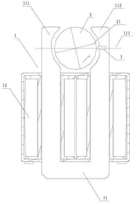
[0025] The basic electromagnetic structure of the miniature permanent magnet synchronous motor in the embodiment of the present invention is as follows: figure 1 As shown, it inherits from the specification of CN201110100111.6 figure 1 ,include:

[0026] ——The stator 1 is mainly composed of a U-shaped iron core 11 and a winding 12; the upper part of the iron core 11 is formed to surround the left and right poles of the rotor 2—the left pole 111 and the right pole 112; the winding 12 is formed by penetrating into the yoke of the iron core 11 The left arm and the right arm each have one coil connected in series or in parallel;

[0027] ——The rotor 2 is a permanent magnet rotor, magnetized by a radially symmetrical sine wave to N and S poles, inserted...


PUM


Abstract

An electronically controlled directionally rotating single-phase self-starting permanent-magnet synchronous motor comprises a stator, a permanent-magnet rotor, a power electronic circuit and a control circuit; and an alternating-current power supply outputs voltage to the stator via the power electronic circuit. The control circuit comprises a detection circuit and a position sensor; the detection circuit is used for detecting the state of the alternating-current power supply; the position sensor is mounted nearby the periphery of the rotor to detect the state of the permanent-magnet rotor; and according to the output of the detection circuit and the output of the position sensor, the power electronic circuit is controlled. The output of the detection circuit includes the transient cycle time of the alternating-current power supply; the output of the position sensor includes the frequency of the magnetic poles of the rotor passing by the position sensor; and when the frequency of the magnetic poles of the rotor passing by the position sensor in a cycle of specified frequency is two times higher than the cycle frequency, the power electronic circuit decreases the voltage outputted to the stator and keeps the voltage at a specified value. The motor can keep optimal performance, however, no-load running vibration, noise and temperature rise are remarkably improved, and the structure is simpler and more reliable.

Description

technical field [0001] The invention relates to an electronically controlled directional rotation single-phase self-starting permanent magnet synchronous motor, in particular to the motor directly driving a small-power centrifugal water pump. In the international patent classification table, the classification can belong to H02P6 / 00. Background technique [0002] The electronically controlled directional rotation single-phase self-starting permanent magnet synchronous motor can be found in the prior patent application CN201110100111.6 of the designer of the present invention. Compared with the asynchronous motor used before, this motor is obviously energy-saving and material-saving, but its vibration, noise and temperature rise are high during no-load operation, so it needs to be improved. Contents of the invention [0003] The technical problem to be solved by the present invention is to propose an electronically controlled directional rotation single-phase self-starting ...

Claims


Application Information

Patent Timeline
Patent Type & Authority Applications(China)
IPC IPC(8): H02P6/08H02P6/16H02P6/17
Inventor 卓春光
Owner HANYU GRP CO LTD
Why Eureka
Try Eureka