Small centrifugal pump driven by electronically controlled single-phase self-starting permanent magnet synchronous motor

An electronic control, permanent magnet synchronous technology, applied in the direction of a single motor speed/torque control, motor control, mechanical energy control, etc., can solve problems such as temperature rise and high noise

Active Publication Date: 2017-10-24
JIANGMEN SUNYA MOTOR CO LTD
View PDF5 Cites 0 Cited by
  • Summary
  • Abstract
  • Description
  • Claims
  • Application Information

AI Technical Summary

Problems solved by technology

[0002] The electronically controlled single-phase self-starting permanent magnet synchronous motor-driven small centrifugal pump disclosed in the previous application CN201210278112.4 is not only energy-saving and material-saving than previous products, but also overcomes vibration, noise and high temperature rise during light-load operation. High problem, but need to set a separate rotor position detection element

Method used


Image

  • Small centrifugal pump driven by electronically controlled single-phase self-starting permanent magnet synchronous motor
  • Small centrifugal pump driven by electronically controlled single-phase self-starting permanent magnet synchronous motor
  • Small centrifugal pump driven by electronically controlled single-phase self-starting permanent magnet synchronous motor

Examples


Embodiment Construction

[0018] The basic mechanical structure of the centrifugal pump in the embodiment of the present invention is as follows: Figure 4 shown, including:

[0019] - motor 2 fixed to the casing;

[0020] ——Centrifugal impeller 1 directly connected to the output shaft of the motor and rotating counterclockwise, which has 4 blades; the number of blades can also be 3, 5 or 6, but preferably not more than 8, and as odd as possible , to reduce vibration noise. The impeller is injection molded with a diameter of 100mm. The impeller should not be larger, and the moment of inertia should be as small as possible to match the starting torque of the motor 2 which is still not too large;

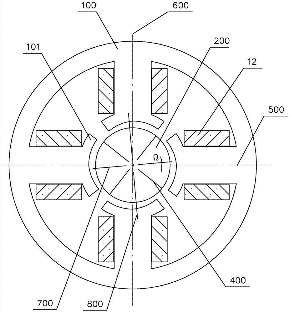
[0021] ——The motor 2 is an inner rotor motor, including a stator 100 and a permanent magnet rotor 200 .

[0022] The basic electromagnetic structure of the motor of the centrifugal pump in the embodiment of the present invention is as follows: figure 1 shown, including:

[0023] ——The rotor 200 is a 4-po...


PUM


Abstract

A small-sized electronically-controlled centrifugal pump driven by a single-phase self-starting permanent-magnet synchronous motor comprises an impeller, an electric motor, a stator winding and a control circuit, wherein the impeller rotates in accordance with a predetermined direction; the electric motor comprises a stator and a permanent-magnet rotor, and the width of a gap between the rotor and the stator is narrowed with a set peripheral direction of a lower edge of each pole; the stator winding has a specified winding direction and is connected to an AC power supply through a switch; the control circuit comprises a detection circuit and a built-in program driving the switch to control an input winding of the AC power supply according to a signal detected by the circuit; and the built-in program is provided with a time frame with current of zero and detection, the detection comprises detecting an end voltage of the winding at the time frame, and the control circuit reduces the voltage output to the winding when the end voltage is monotonic according to frames and no zero-crossing value occurs. By the design, the vibration, the noise and the temperature rise during light-load running can be improved, an independent rotor position detection component is not needed, thus, the cost is reduced, and more reliability is achieved.

Description

technical field [0001] The present invention relates to a small centrifugal pump driven by an electronically controlled single-phase self-starting permanent magnet synchronous motor, especially relates to the cooperation of its mechanical structure, electromagnetic structure and control method; in the international patent classification table, the classification belongs to F04D25 / 06 or F04D27 / 00 . Background technique [0002] The electronically controlled single-phase self-starting permanent magnet synchronous motor-driven small centrifugal pump disclosed in the previous application CN201210278112.4 is not only energy-saving and material-saving than previous products, but also overcomes vibration, noise and high temperature rise during light-load operation. High problem, but a separate rotor position detection element needs to be set. Contents of the invention [0003] The technical problem to be solved by the present invention is to propose a small centrifugal pump driv...

Claims


Application Information

Patent Timeline
Patent Type & Authority Patents(China)
IPC IPC(8): H02P6/26H02P6/08H02P6/18H02K1/14H02K7/14F04D13/06
CPCF04D13/06H02K1/146H02K7/14H02K2201/03H02P6/08H02P6/18H02P2207/05
Inventor 叶露微
Owner JIANGMEN SUNYA MOTOR CO LTD
Why Eureka
Try Eureka