Electronically-controlled U-shaped iron core single-phase permanent-magnet synchronous motor-driven centrifugal pump

A synchronous motor and single-phase permanent magnet technology, applied in the field of centrifugal pumps, can solve problems such as temperature rise and loud noise

Active Publication Date: 2015-12-30
HANYU GRP CO LTD
View PDF6 Cites 6 Cited by
  • Summary
  • Abstract
  • Description
  • Claims
  • Application Information

AI Technical Summary

Problems solved by technology

[0002] The electronically controlled U-shaped iron core single-phase permanent magnet synchronous motor-driven centrifugal pump disclosed in the prior application CN201210278112.4 is not only energy-saving and material-saving than previous products, but also can overcome vibration, noise and temperature rise when running without water. Higher problem, but requires a separate rotor position detection element

Method used


Image

  • Electronically-controlled U-shaped iron core single-phase permanent-magnet synchronous motor-driven centrifugal pump
  • Electronically-controlled U-shaped iron core single-phase permanent-magnet synchronous motor-driven centrifugal pump
  • Electronically-controlled U-shaped iron core single-phase permanent-magnet synchronous motor-driven centrifugal pump

Examples


Embodiment Construction

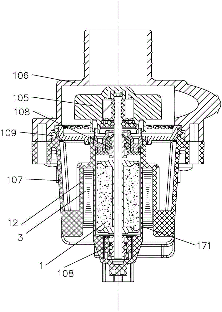
[0019] The basic mechanical structure of the centrifugal pump in the embodiment of the present invention is as follows: figure 1 shown, including:

[0020] ——U-shaped core single-phase permanent magnet synchronous motor ( figure 1 It shows the laminated iron core 3 and winding 12 of the motor stator and the section of the permanent magnet rotor 1) and the centrifugal impeller 105 coaxially driven by a starting mechanism. The centrifugal impeller 105 has four blades. The number of blades can also be 3, 5 or 6, but preferably not more than 8, and if an odd number of blades is used, it is more conducive to reducing vibration and noise. The impeller is injection molded and has a diameter of 60mm. The impeller should not be too large so that the moment of inertia is too large, so as to cooperate with the not too large starting torque of the motor; but it should not be too small, so as to have enough moment of inertia to adapt to the present invention.

[0021] - the pump cover ...


PUM


Abstract

The invention discloses an electronically-controlled U-shaped iron core single-phase permanent-magnet synchronous motor-driven centrifugal pump. The diameter of the impeller is 20-70 mm; the width of an air gap between a U-shaped iron core and a permanent magnet rotor of a motor is reduced at the lower ends of all poles in the set circumferential direction; a stator winding is connected to an alternating current power supply through a switch in the regular winding direction; a control circuit comprises a detection circuit and a built-in program used for driving the switch according to a signal detected by the detection circuit so as to control the current input into the winding by the alternating current power supply; the built-in program has a time period for enabling the current to be zero and detection comprising detection of a terminal voltage of the winding at the time period; in addition, when the terminal voltage is monotonous and has no value larger than zero, the control circuit lowers the voltage output to the winding. Through the design, vibration, noise and temperature rise during anhydrous operation are improved and a rotor position detecting element is not required to be arranged separately, so that the cost is reduced and higher reliability is realized.

Description

technical field [0001] The present invention relates to a centrifugal pump driven by an electronically controlled U-shaped iron core single-phase permanent magnet synchronous motor, especially the cooperation of its impeller machinery, electromagnetic structure and control method; in the international patent classification table, the classification belongs to F04D25 / 06 or F04D27 / 00. Background technique [0002] The electronically controlled U-shaped iron core single-phase permanent magnet synchronous motor-driven centrifugal pump disclosed in the prior application CN201210278112.4 is not only energy-saving and material-saving than previous products, but also can overcome vibration, noise and temperature rise when running without water. Higher problem, but need to set a separate rotor position detection element. Contents of the invention [0003] The technical problem to be solved by the present invention is to propose a centrifugal pump driven by an electronically contr...

Claims


Application Information

Patent Timeline
Patent Type & Authority Applications(China)
IPC IPC(8): F04D13/06F04D29/22F04D15/00H02K21/14
Inventor 区长钊李子宏
Owner HANYU GRP CO LTD
Why Eureka
Try Eureka