
Electric vehicle drive control apparatus

An electric locomotive and electric control technology, which is applied to control devices, electric devices, electric braking systems, etc., can solve the problems of deterioration of vehicle ride feel, decrease in deceleration, and prolongation of braking distance, so as to improve ride feel, reduce Effects of small deceleration changes

Active Publication Date: 2012-11-21
MITSUBISHI ELECTRIC CORP
View PDF6 Cites 7 Cited by
  • Summary
  • Abstract
  • Description
  • Claims
  • Application Information

AI Technical Summary

Problems solved by technology

However, since the mechanical brake uses air pressure to press the brake pads against the wheel, etc., and uses friction to obtain the braking force, it takes time for the mechanical brake to fully function.
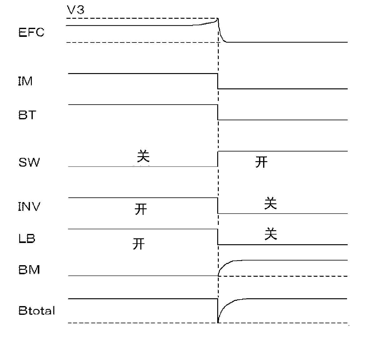
Although in normal driving of an electric locomotive, when the regenerative brake is switched off (OFF) and transferred to the mechanical brake, by gradually reducing the regenerative braking force, the mechanical braking force gradually works during this period, it is possible to maintain the basic braking force of the electric locomotive However, as mentioned above, when the regenerative braking force is lost momentarily, the total braking force (Btotal) of the electric locomotive is insufficient during the period until the mechanical brake works, so the phenomenon that the deceleration drops sharply occurs
In such a case, there is a problem that the ride quality of the vehicle deteriorates and the braking distance increases due to fluctuations in deceleration.

Method used


Image

  • Electric vehicle drive control apparatus
  • Electric vehicle drive control apparatus
  • Electric vehicle drive control apparatus

Examples


Embodiment approach 1

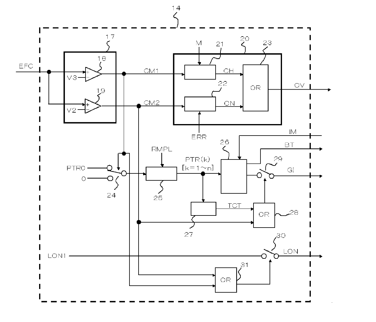
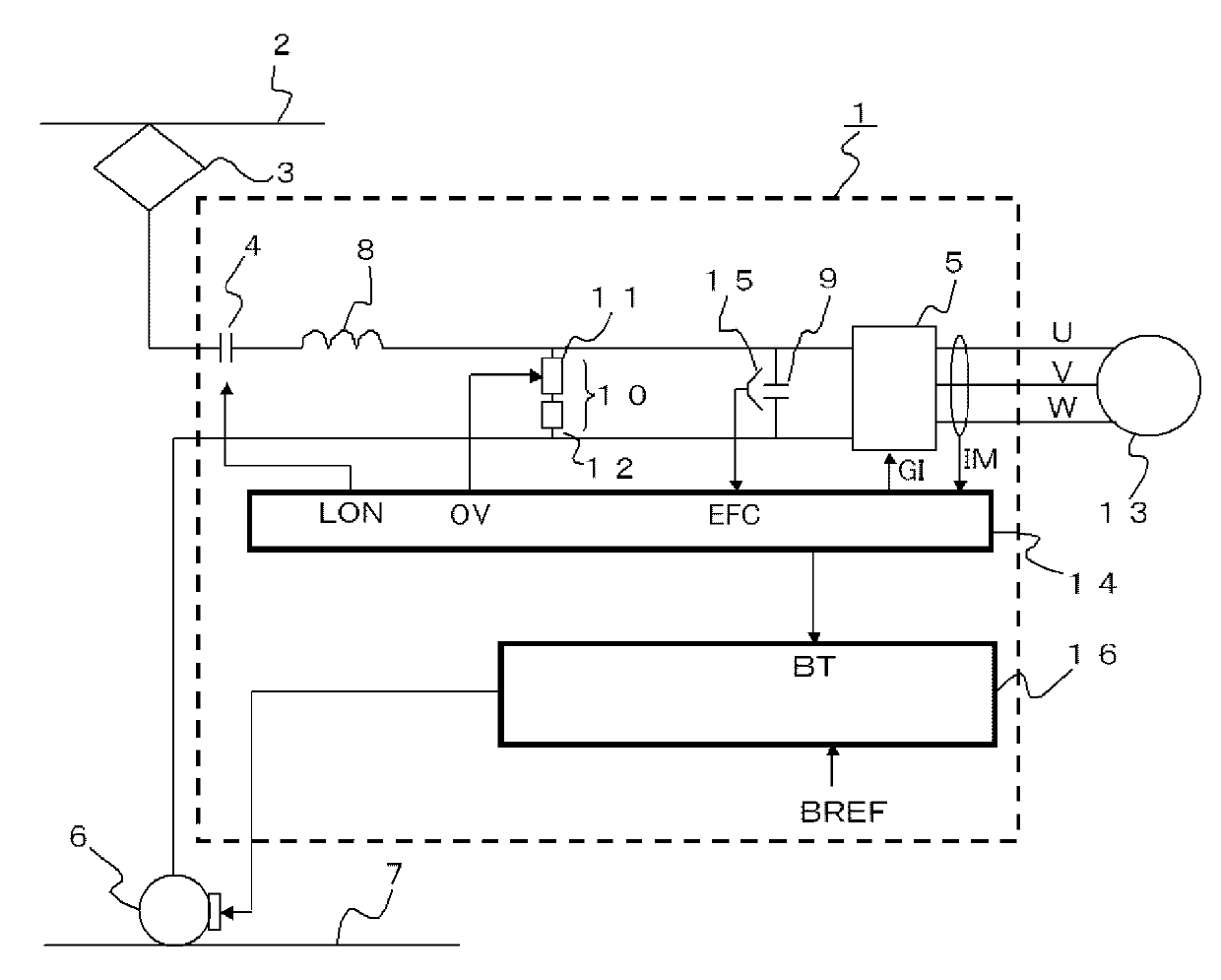
[0019] figure 1 It is a diagram showing a configuration example of the drive control device 1 for an electric vehicle according to Embodiment 1 of the present invention. Such as figure 1 As shown, the power collector 3 is brought into contact with the overhead line 2, and direct current from a substation (not shown) is input to the drive control device 1 . The DC power is input to an inverter circuit 5 as a power conversion unit via a chopper 4 as a switch unit for connecting or opening the DC power. The return current from the drive control device 1 flows through the rail 7 via the wheels 6 and returns to the negative side of the substation (not shown).

[0020] An input filter composed of a reactor 8 and a filter capacitor 9 is provided in the drive control device 1; and is used to protect the inverter circuit 5 when the regenerative load is insufficient and the input voltage rises abnormally during the regenerative braking operation, At the same time, even when the cut...

Embodiment approach 2

[0072] The drive control device for an electric vehicle according to this embodiment uses a storage battery instead of the discharge resistor 12 of the capacitor voltage regulator 10 . The configuration and operation of the other devices are the same as those in Embodiment 1, so descriptions are omitted. According to the driving control device of the electric locomotive according to the present embodiment, in addition to the effect achieved by the driving control device 1 of the first embodiment, there is also an effect that when the regenerative load is insufficient during the regenerative braking operation, the regenerative current is used to charge the battery. Charging is performed, and since the electric power charged to the storage battery can be used to drive the electric locomotive, the energy utilization efficiency when the electric locomotive is running can be improved.


PUM


Abstract

Provided is an electric vehicle drive control apparatus, wherein fluctuation in the decelerating rate of the electric vehicle is made to be smaller, and the ride thereon is improved to become more comfortable, even when regeneration load is insufficient while regenerative braking is being activated. The electric vehicle drive control apparatus (1) is provided with an open / close unit (4) that opens or closes a connection with DC power; a power conversion unit (5), to which DC power is inputted to two input terminals thereof via the open / close unit, which converts DC power to AC power by a switching operation, and drives an AC rotating machine (13) connected to the output side thereof; and a voltage detection unit (15) that detects the voltage between the two terminals. The electric vehicle drive control apparatus (1) is also provided with a power control unit (14) that controls the power conversion unit such that the open / close unit is opened when the voltage detected by the voltage detection unit exceeds a prescribed opening voltage, and the regenerative braking force of the AC rotating machine is reduced with a prescribed reduction pattern having a ramp reduction period that is longer than 0.

Description

technical field [0001] The invention relates to a drive control device for propulsion control of an electric locomotive. Background technique [0002] Generally, an electric locomotive is configured to take in electric power from an overhead line by a power collector, and use the taken in electric power to drive an AC rotating machine by a drive control device using an inverter circuit or the like. . In addition, when braking a vehicle, so-called regenerative braking is used in which a braking force is obtained by regeneratively operating an AC motor. The regenerative electric power generated at this time is supplied to other powered vehicles existing near the own vehicle or the load of the own vehicle via the overhead line or the third rail, and then it is consumed. [0003] However, there may be cases where there are no other vehicles in the vicinity of the vehicle in the morning or evening or in an idle line area where the number of train lines is small. fully consumed...

Claims


Application Information

Patent Timeline
IPC IPC(8): B60L7/14B60L3/00B60L7/24
CPCB60L2200/26B60L9/22B60L2240/429B60L7/26B60L7/14B60L7/18B60L7/10Y02T10/642Y02T10/64B60Y2200/91B60Y2400/3086
Inventor 草野健一
Owner MITSUBISHI ELECTRIC CORP
Learn More