Air spring stiffness controller

Inactive Publication Date: 2005-04-26
VOLVO TRUCKS NORTH AMERICA
View PDF23 Cites 29 Cited by
  • Summary
  • Abstract
  • Description
  • Claims
  • Application Information

AI Technical Summary

Benefits of technology

[0004]A heavy duty truck suspension system having air springs whose stiffness characteristics can be adjusted according to operating parameters can provide an improved ride According to an embodiment of the invention, an apparatus is provided for adaptively controlling relative motion between the wheels and the frame of a heavy duty truck having a frame suspended on wheels by a suspension system. An air spring is disposed between the frame and at least one of the wheels having a primary reservoir

Problems solved by technology

While such compensation has diminished the effects of torque reaction and driveline vibrations to provide a relatively comfortable ride during normal operating conditio

Method used


Image

  • Air spring stiffness controller
  • Air spring stiffness controller
  • Air spring stiffness controller

Examples


Example

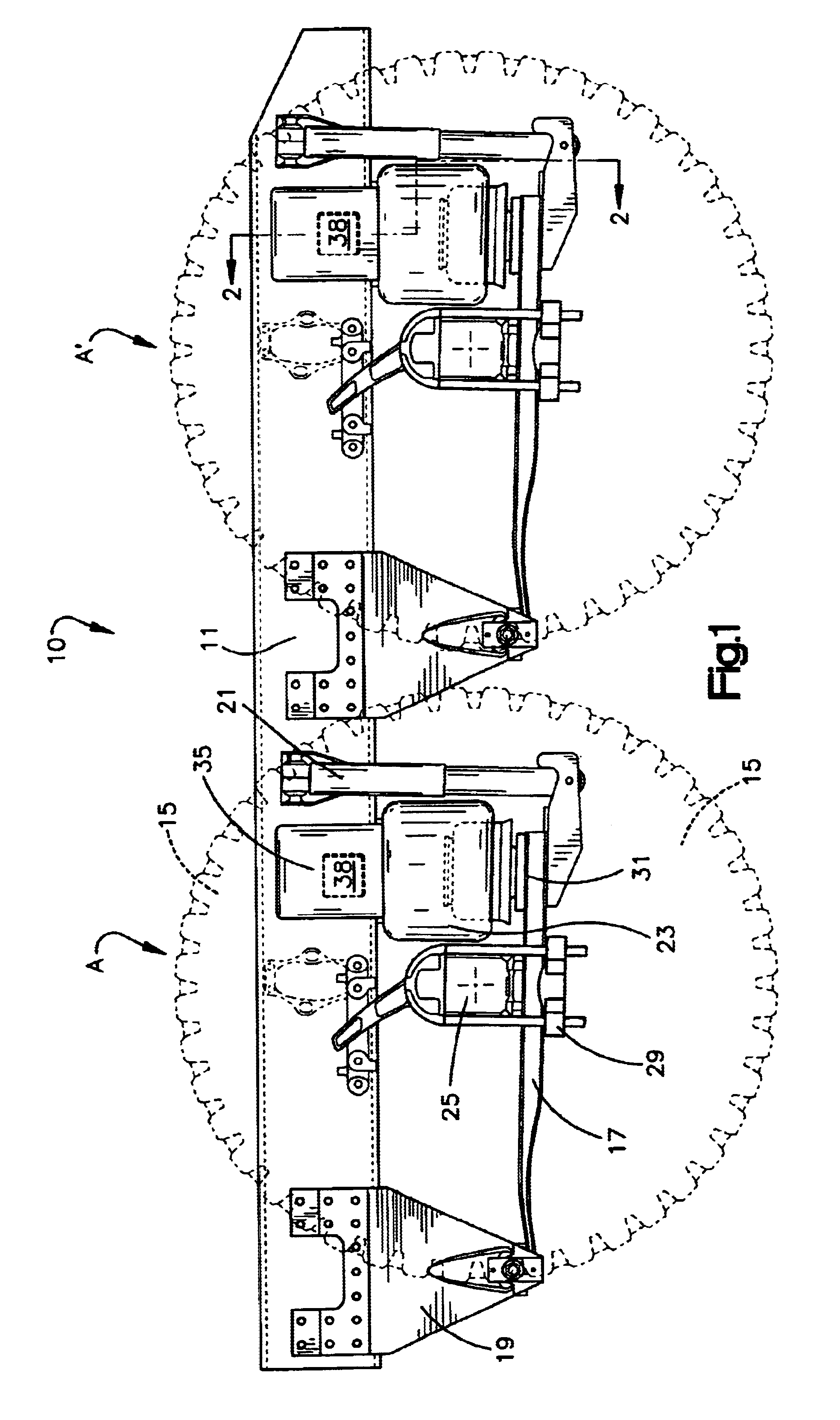
[0013]FIG. 1 depicts a side plan view of a trailing arm torque reactive suspension system 10 associated with a pair of rear wheel sets A and A′ that drive a frame member 11 of a heavy duty truck. The suspension components associated with each wheel set are the same. The basic components of the suspension system 10 should be familiar to one of skill in the art and will only be outlined generally below.

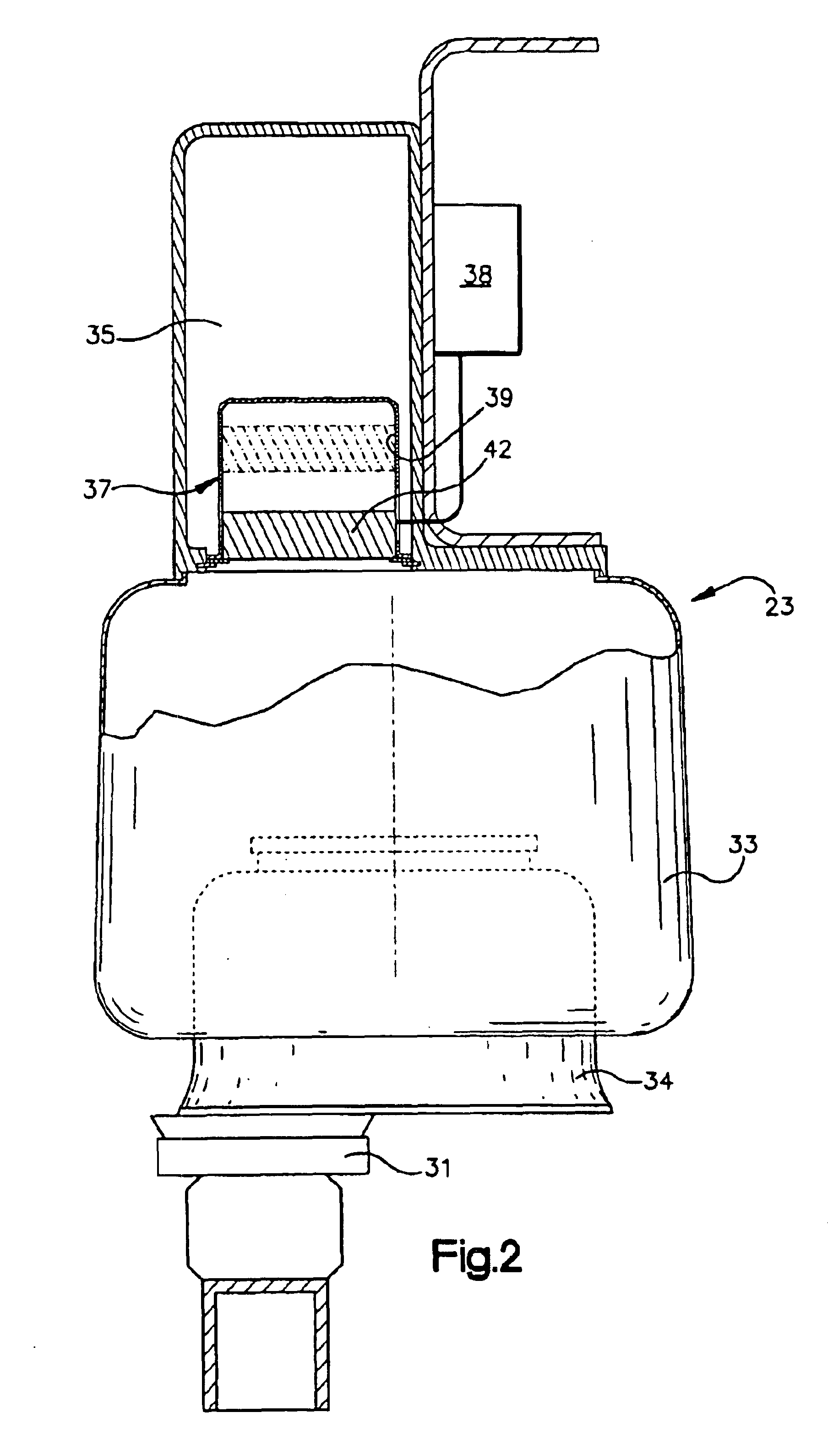
[0014]The suspension system 10 includes a main support member 17 that is pivotally connected to the frame 11 by a spring hanger bracket 19. A drive axle 25 is attached to the main support member using a U bolt 29. A shock absorber 21 is connected between the main support member 17 and the frame member 11 to damp the rise and fall of the frame of the vehicle with respect to the road. An air spring 23 (shown in more detail in FIG. 2) is bolted at its base to a base bracket 31 which is in turn connected to the main support member 17. The top of the air spring 23 is attached to the adjacent...


PUM


Abstract

A method and apparatus for adaptively damping relative motion between the wheels and the frame of a heavy duty truck having a frame suspended on wheels by a suspension system. An air spring is disposed between the frame and at least one of the wheels having a primary reservoir for holding air and a piston adapted to act upon the air in the reservoir to compress the air and thereby provide support for the frame. An auxiliary reservoir holds air and can be placed in fluid communication with the primary reservoir to increase an effective volume of air upon which the piston acts. A control valve selectively places the auxiliary reservoir in communication with the primary reservoir based on vehicle operating parameters. The control valve can be actuated mechanically by forces acting on the wheels or by a controller that controls the valve based on wheel torque and road roughness.

Description

TECHNICAL FIELD[0001]The invention relates generally to suspension systems for over the highway, heavy duty trucks and more particularly to a locking suspension system that varies the stiffness of suspension components in response to operating conditions.BACKGROUND OF THE INVENTION[0002]The frames of heavy duty trucks are typically suspended on torque reactive rear suspensions. Commonly, these suspensions provide a leaf or air spring to maintain a constant vehicle height. As drive train systems are optimized to provide greater torque output, suspensions in general have been made stiffer to compensate for torque reaction and driveline vibrations that are associated with the higher torques. While such compensation has diminished the effects of torque reaction and driveline vibrations to provide a relatively comfortable ride during normal operating conditions, the stiffer suspensions cannot absorb high impact forces such as those caused by rough roads and as a result do not provide ade...

Claims


Application Information

Patent Timeline
IPC IPC(8): B60G11/28B60G17/015B60G17/04B60G11/30B60G11/26B60G17/0165B60G17/052B60G11/27
CPCB60G11/27B60G11/30B60G17/0155B60G17/0165B60G17/0521B60G11/28B60G2800/95B60G2200/31B60G2200/341B60G2202/152B60G2202/154B60G2204/126B60G2204/143B60G2204/148B60G2204/4302B60G2204/4306B60G2204/44B60G2204/45B60G2206/424B60G2300/0262B60G2400/204B60G2400/32B60G2400/38B60G2400/51222B60G2400/821B60G2500/2041B60G2500/30B60G2800/162B60G2800/214B60G2800/916
Inventor SVARTZ, BJORN O.WHITE, DARRIS
Owner VOLVO TRUCKS NORTH AMERICA
Why Eureka
Try Eureka