permanent magnet rotating machines

A permanent magnet and rotating electrical machine technology, applied in synchronous motors with stationary armatures and rotating magnets, magnetic circuit rotating parts, magnetic circuit shape/style/structure, etc., can solve problems such as size limitations and reduce leakage Effects of magnetic flux, increased maximum torque, and improved performance

Active Publication Date: 2016-05-25
YASKAWA DENKI KK
View PDF7 Cites 0 Cited by
  • Summary
  • Abstract
  • Description
  • Claims
  • Application Information

AI Technical Summary

Problems solved by technology

A part of the magnetic flux generated by the permanent magnet becomes the leakage magnetic flux returning to the permanent magnet from the connection part 2c on both sides of the through hole through the inner bridge part of the rotor core, but the size is limited because the through hole is provided.

Method used


Image

  • permanent magnet rotating machines
  • permanent magnet rotating machines
  • permanent magnet rotating machines

Examples


no. 1 example

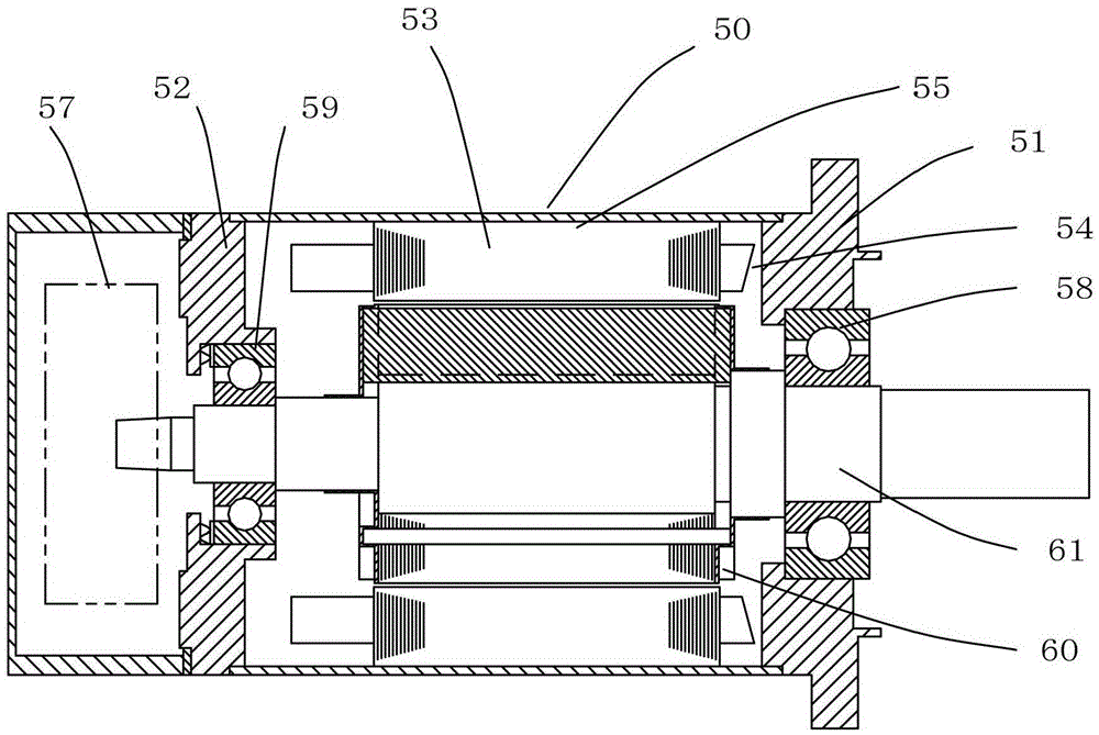
[0063] figure 1 It is an axial sectional view showing a permanent magnet type rotating electrical machine according to a first embodiment of the present invention used in an AC servo motor.

[0064] In the figure, the rotating electrical machine includes a stator and a substantially cylindrical rotor 60 rotatably supported. The rotor is rotatably supported by the load-side bracket 51 and the non-load-side bracket 52 via the load-side bearing 58 and the non-load-side bearing 59 .

[0065] An encoder unit 57 for detecting the rotational position of the rotor is provided at the non-load end portion of the shaft 61 .

[0066] The stator is composed of a stator core 53 and a stator coil 54 .

[0067] The non-load side bracket is fastened to the load side bracket with the frame 50 by unillustrated bolts.

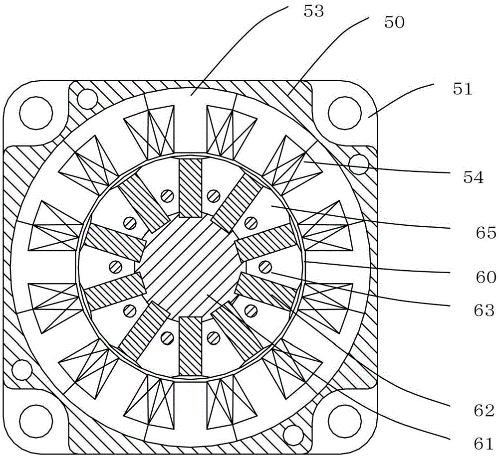
[0068] figure 2 is a radial sectional view of the rotating electric machine.

[0069] In the figure, the stator is composed of a stator core 53 divided into individual teet...


PUM


Abstract

A permanent magnet rotating electrical machine includes a stator and a rotatable, approximately cylindrical rotor. The rotor includes a shaft, rotor cores, radial permanent magnets, and side plates. The shaft includes projected and depressed engagement portions. The rotor cores are separated from each other on a magnetic pole basis. The rotor cores constitute circumferentially arranged pole shoes. The radial permanent magnets are each on a circumferential side of a pole shoe among the pole shoes. Each of the radial permanent magnets is engaged with an engagement portion among the engagement portions of the shaft. The side plates are on axial ends of the rotor. The side plates support the rotor cores and the permanent magnets in a radial direction of the rotor.

Description

technical field [0001] The present invention relates to rotating electrical machines such as AC servo motors, and more particularly to the structure of rotors. Background technique [0002] In a conventional permanent magnet type rotating electrical machine including a stator and a substantially cylindrical rotor rotatably supported, the rotor has: a rotor core constituting pole shoes arranged in a circumferential shape; and permanent magnets. , which are arranged radially on both sides of each pole piece and the number is the same as the number of poles, and guide the magnetic flux generated by the permanent magnet to the outer periphery of the pole piece to obtain magnetic poles (for example, refer to Patent Document 1). [0003] Figure 7 It is a radial cross-sectional view of a rotor of a conventional permanent magnet type rotating electrical machine, and is a structural example of a permanent magnet type rotating electrical machine including a stator and a substantially...

Claims


Application Information

Patent Timeline
Patent Type & Authority Patents(China)
IPC IPC(8): H02K1/27H02K1/22
CPCH02K1/2773H02K1/27H02K1/276H02K1/28H02K21/12H02K21/14
Inventor 野中刚
Owner YASKAWA DENKI KK
Why Eureka
Try Eureka