Transfer machine middle groove and transfer machine

A technology of reloading machine and groove side, which is applied in the direction of conveyor, slitting machine, earthwork drilling and mining, etc. It can solve the problems of inability to guarantee the fixity of the curved section, increase the difficulty of supporting along the groove, and increase the cost of excavation, so as to meet the requirements of bending The effect of meeting the requirement of segment fixity, reducing the difficulty of support and reducing the cost of excavation

Active Publication Date: 2012-11-28
SANY HEAVY EQUIP
View PDF5 Cites 0 Cited by
  • Summary
  • Abstract
  • Description
  • Claims
  • Application Information

AI Technical Summary

Problems solved by technology

[0007] 1) The width of the transport channel is too wide, which not only increases the difficulty of supporting the channel, but also increases the cost of excavation;
[0008] 2) The horizontal direction adaptation angle of the connection between adjacent middle grooves is small, and the bending requirements of the reloading machine cannot be realized within a short distance
[0009] 3) When the transfer machine is advancing with the working face, it cannot guarantee the fixity of the bending section

Method used


Image

  • Transfer machine middle groove and transfer machine
  • Transfer machine middle groove and transfer machine
  • Transfer machine middle groove and transfer machine

Examples


Embodiment Construction

[0040] In order to understand the above purpose, features and advantages of the present invention more clearly, the present invention will be further described in detail below in conjunction with the accompanying drawings and specific embodiments. In the case of no conflict, the embodiments of the application and the features in the embodiments can be combined with each other.

[0041] In the following description, many specific details are set forth in order to fully understand the present invention. However, the present invention can also be implemented in other ways different from those described here. Therefore, the protection scope of the present invention is not limited by the specific details disclosed below. EXAMPLE LIMITATIONS.

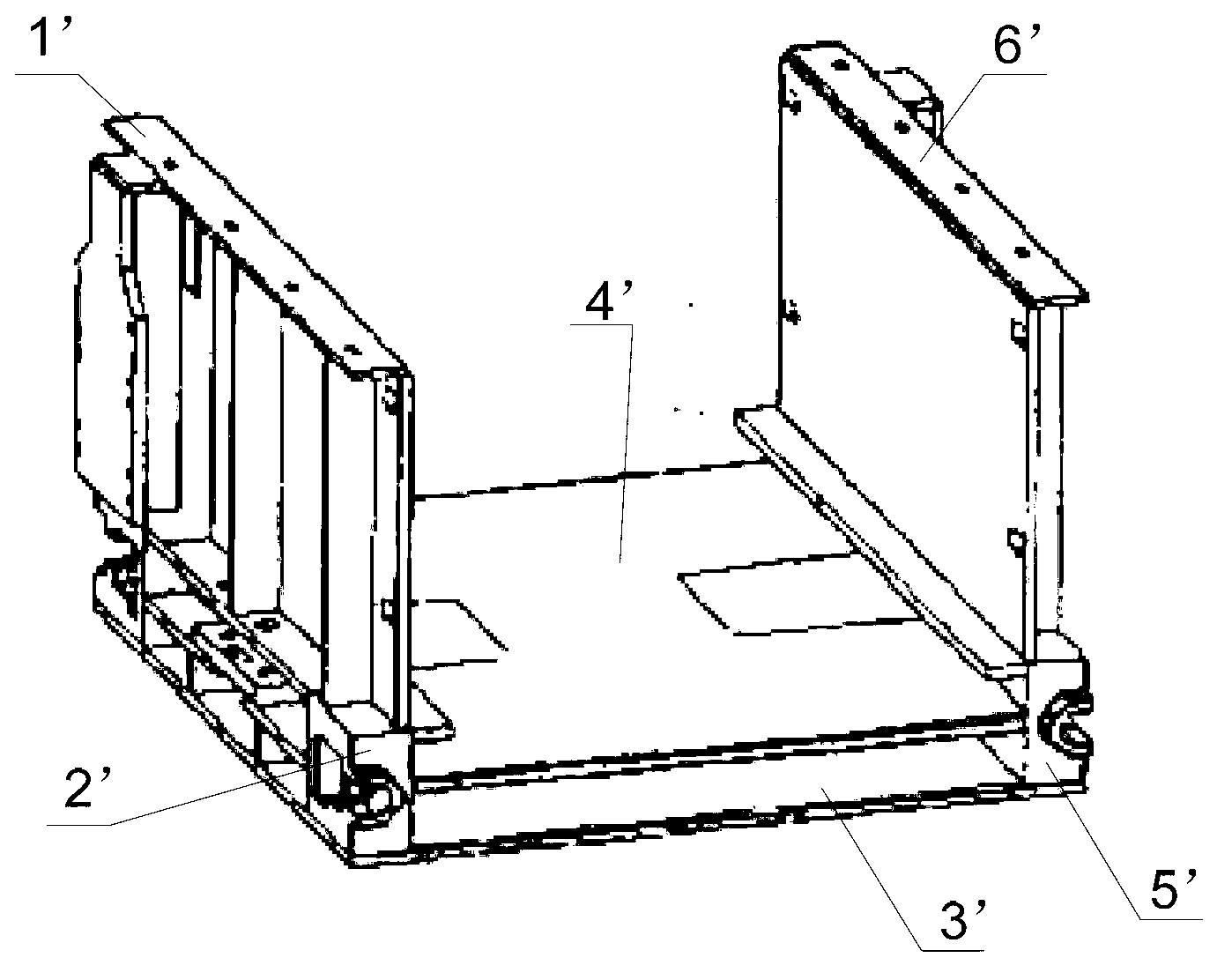
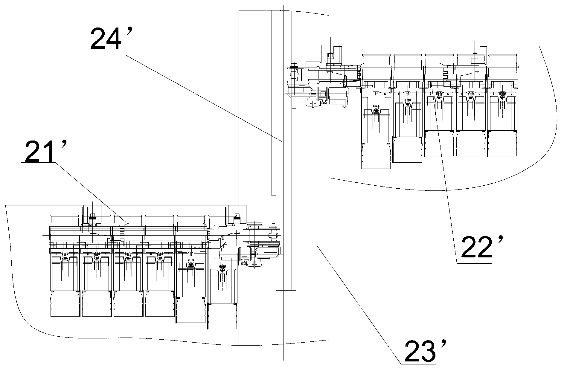
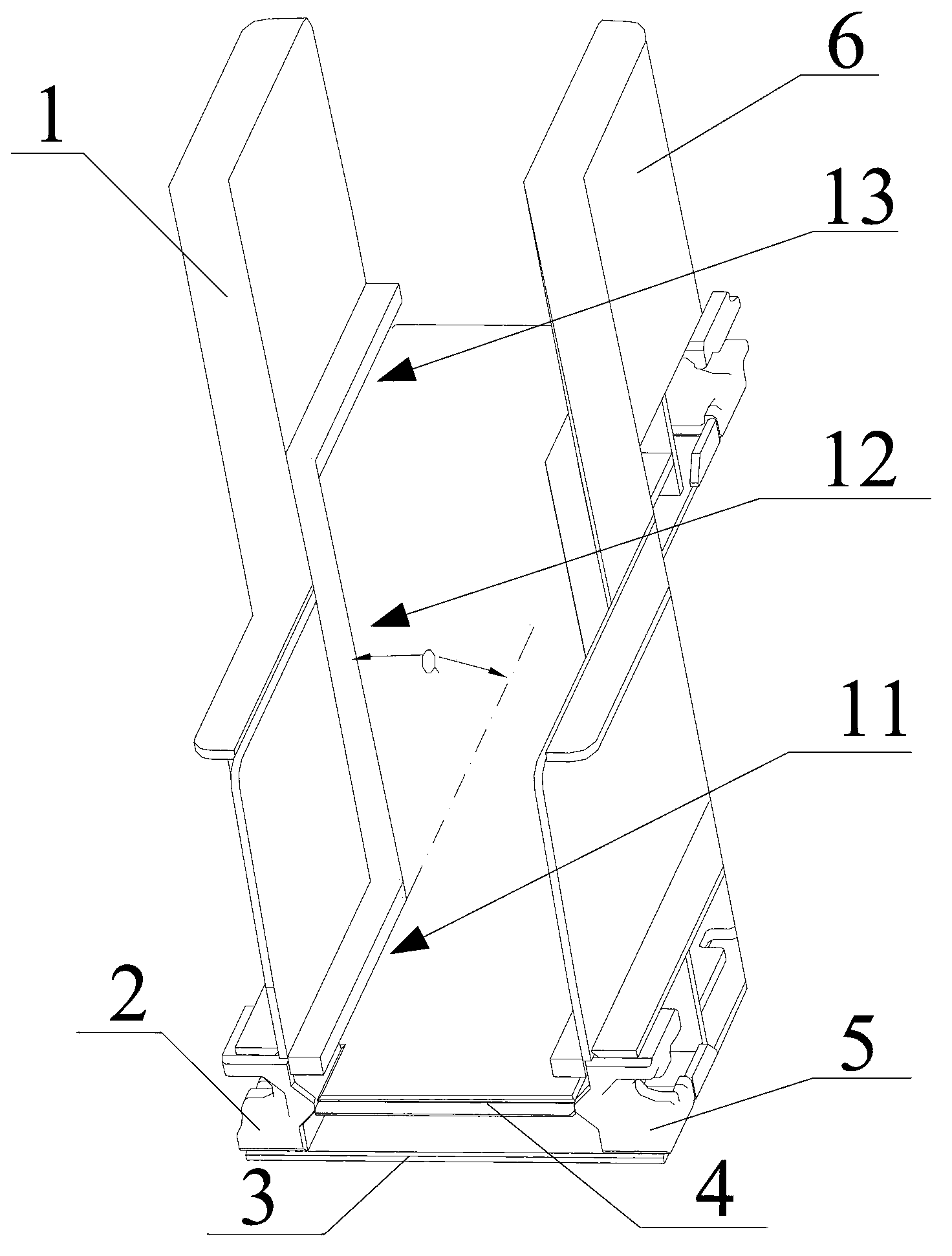
[0042] image 3It is a structural schematic diagram of an embodiment of the middle tank of the transfer machine according to the present invention, Figure 4 is installed image 3 The schematic diagram of the layout of the loader and the t...


PUM


Abstract

The invention provides a transfer machine middle groove which comprises a first baffle, a first groove ledge, a middle plate, a bottom plate, a second groove ledge and a second baffle, wherein the bottom plate and the middle plate are fixedly connected with the first groove ledge and the second groove ledge respectively; the middle plate is positioned above the bottom plate; and the first baffle and the second baffle are fixedly connected with the first groove ledge and the second groove ledge respectively. The transfer machine middle groove further comprises a first section, a second section and a third section, wherein the second section is positioned between the first section and the third section; both ends of the second section are fixedly connected with one end of the first section and one end of the third section; and the first section and the third section are mutually parallel straight sections, but are not positioned in the same straight line. The invention further provides a transfer machine. As the bent middle groove is adopted, the transfer machine middle groove can meet short distance bending requirements and bent section fixity requirements; and in addition, the width of a transport gate road is reduced when the unloading distance between a scraper conveyer head and the transfer machine is ensured, therefore, the support difficulty and tunneling cost of the transport gate road are reduced.

Description

technical field [0001] The invention relates to the field of coal mining, in particular to a transfer machine middle slot and a transfer machine including the transfer machine middle slot. Background technique [0002] At present, as the intermediate reloading equipment of mining and tunneling coal transportation systems, the reloader is usually arranged in the transport trough of the fully mechanized mining face. It is a heavy-duty scraper conveyor that can move longitudinally as a whole. The propulsion of the coal mining face and the expansion and contraction of the belt conveyor move as a whole. [0003] The coal mining technology of the opposite-drawing working face is suitable for the long-wall working face with a large length, and overcomes the limitation of the laying length of the scraper conveyor to a certain extent. The coal mining process includes: arranging two return air chutes and a common transport chute side by side, and the working face between adjacent chu...

Claims


Application Information

Patent Timeline
Patent Type & Authority Applications(China)
IPC IPC(8): B65G19/28E21C35/20
Inventor 赵长海王启佳金全
Owner SANY HEAVY EQUIP
Why Eureka
Try Eureka