Method for testing microwave dielectric property of high-loss dielectric substance

A dielectric material, microwave dielectric technology, applied in the direction of measuring resistance/reactance/impedance, measuring electrical variables, measuring devices, etc., can solve the problems of decreased test accuracy, unconsidered, and inability to guarantee test accuracy, and achieve high-precision testing. Effect

Active Publication Date: 2012-11-28
ZHEJIANG UNIV
View PDF4 Cites 24 Cited by
  • Summary
  • Abstract
  • Description
  • Claims
  • Application Information

AI Technical Summary

Problems solved by technology

For the former two, the scattering parameters at a single frequency point are directly used to calculate the dielectric properties, and as the dielectric constant increases, the scattering parameters are less and less sensitive to the change of the dielectric constant, so the test The accuracy also drops sharply; the resonant cavity perturbation method utilizes the characteristics of microwave resonance, and the accuracy is slightly higher, but because the change of the electromagnetic field distribution in the cavity caused by the introduction of the sample is not considered, it is also unable to guarantee that the dielectric constant is high. test accuracy

Method used


Image

  • Method for testing microwave dielectric property of high-loss dielectric substance
  • Method for testing microwave dielectric property of high-loss dielectric substance
  • Method for testing microwave dielectric property of high-loss dielectric substance

Examples


Embodiment 1

[0037] For BaTiO with high dielectric loss 3 The microwave dielectric properties of ferroelectric ceramics were tested.

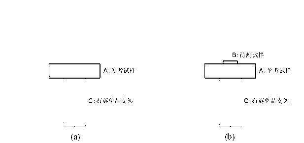
[0038] The sample B to be tested is BaTiO with a diameter of 2mm and a thickness of 0.2mm 3 Ceramic; low loss reference sample A is Ca with a diameter of 12mm and a thickness of 1-5mm 1.15 Nd 0.85 al 0.85 Ti 0.15 o 4 、Ba 2 Ti 9 o 20 and Ba 1.85 SM 4.1 Ti 9 o 24 ceramics.

[0039] The test results are shown in Table 1.
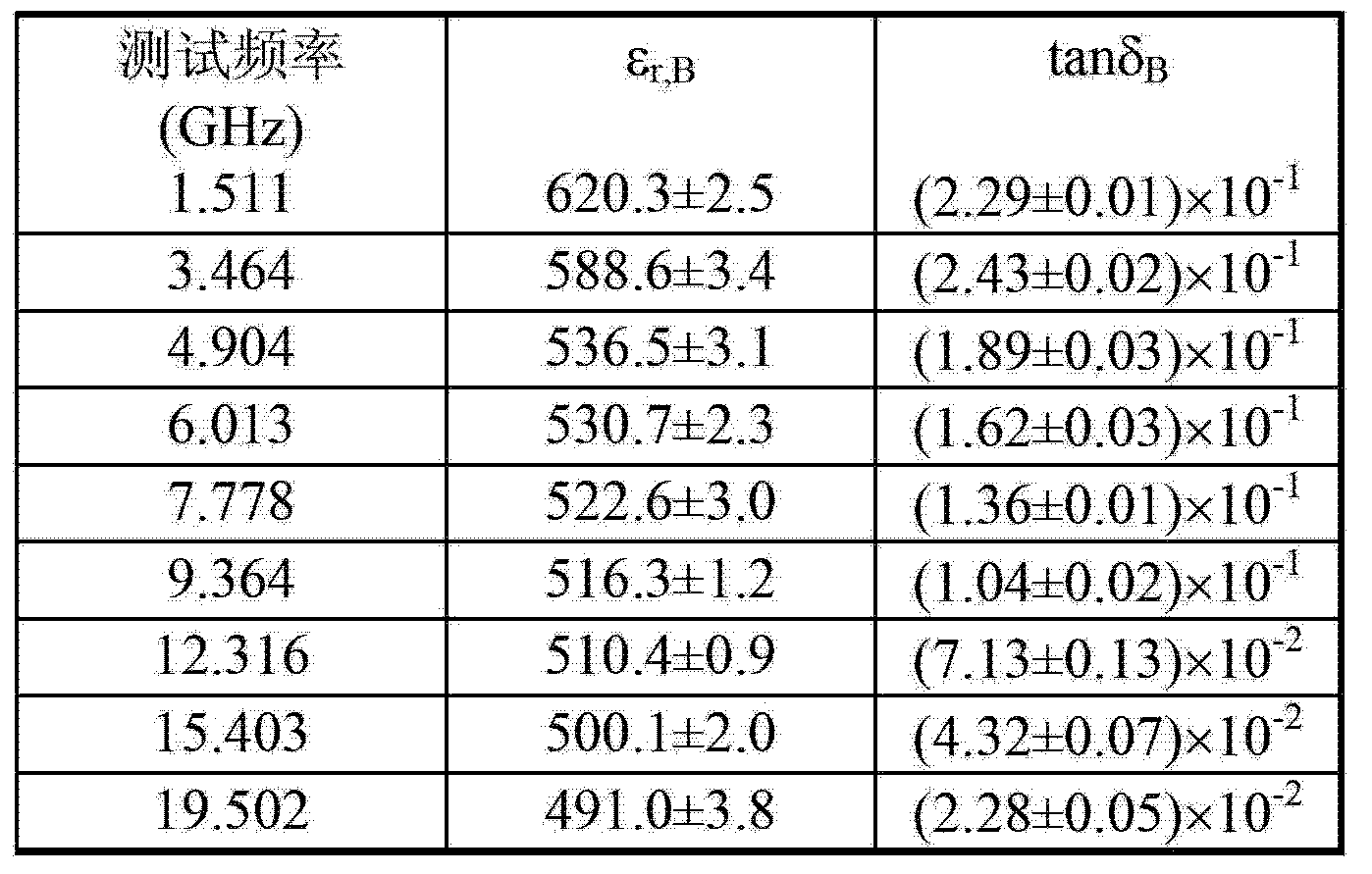
[0040] Table 1

[0041]

[0042] Known by table 1: test BaTiO with the method provided by the invention 3 The microwave dielectric properties of ceramics have good repeatability in the frequency range of 1-20GHz.

Embodiment 2

[0044] For CaCu with high dielectric loss 3 Ti 4 o 12 The microwave dielectric properties of ferroelectric ceramics were tested.

[0045] The sample B to be tested is CaCu with a diameter of 3mm and a thickness of 0.5mm 3 Ti 4 o 12 Ceramic; low loss reference sample A is Ca with a diameter of 12mm and a thickness of 1-5mm 1.15 Nd 0.85 al 0.85 Ti 0.15 o 4 、Ba 2 Ti 9 o 20 and Ba 1.85 SM 4.1 Ti 9 o 24 ceramics.

[0046] The test results are shown in Table 2.

[0047] Table 2

[0048]

[0049] Known by table 2: test CaCu with the method provided by the invention 3 Ti 4 o 12 The microwave dielectric properties of ceramics have good repeatability in the frequency range of 1-20GHz.


PUM


Abstract

The invention discloses a method for testing microwave dielectric property of a high-loss dielectric substance. According to the method, a small-size sample to be tested is used, and a large-size and low-loss reference sample is introduced, so that the high loss of the sample to be tested is reduced, and the resonance peak is ensured to be observed. According to the changes of the resonance peak of a TE01 delta model when only the reference sample is arranged in a resonant cavity and the reference sample and the sample to be tested are simultaneously arranged in the resonant cavity, and the distribution of an electromagnetic field under the two conditions can be simulated by using finite element analysis, so that the dielectric constant and the dielectric loss of the sample to be tested at the resonance frequency can be obtained. According to the method, the characteristics of high test precision of the microwave resonance method is utilized, and the influence on the distribution of the electromagnetic field caused by the introduction of the sample to be tested, is considered, so that the defects of low precision of other conventional methods can be overcome from the test principle, and the accurate test of the microwave dielectric property of the high-loss substance can be realized. Meanwhile, the resonance frequency is decided by the reference sample with large size, so that the frequency conversion test can be realized by changing the dielectric constant or the size of the reference sample.

Description

technical field [0001] The invention belongs to the technical field of microwave testing, in particular to the testing technology of microwave dielectric properties of high-loss dielectric materials. Background technique [0002] High loss (greater than 10 -2 ) Dielectric materials such as ferroelectric materials and giant permittivity materials have important potential application prospects in the microwave frequency band, but their microwave dielectric properties are difficult to accurately test. The test methods for microwave dielectric properties of high loss materials mainly include reflection method, reflection-transmission method and resonant cavity perturbation method. For the former two, the scattering parameters at a single frequency point are directly used to calculate the dielectric properties, and as the dielectric constant increases, the scattering parameters are less and less sensitive to the change of the dielectric constant, so the test The accuracy also d...

Claims


Application Information

Patent Timeline
Patent Type & Authority Applications(China)
IPC IPC(8): G01R27/26
Inventor 李雷陈湘明
Owner ZHEJIANG UNIV
Why Eureka
Try Eureka