Method for increasing testing signal frequency and testing signal generation equipment

A technology for testing signals and generating equipment, applied in electronic circuit testing, components of electrical measuring instruments, measuring electricity, etc. The effect of increasing the test frequency

Inactive Publication Date: 2012-11-28
SHANGHAI HUAHONG GRACE SEMICON MFG CORP
View PDF5 Cites 3 Cited by
  • Summary
  • Abstract
  • Description
  • Claims
  • Application Information

AI Technical Summary

Problems solved by technology

[0004] When it is necessary to generate a square wave signal higher than the highest output frequency (for example, 50M), if the test machine is not improved, the square wave signal higher than the highest output frequency cannot be realized

Method used


Image

  • Method for increasing testing signal frequency and testing signal generation equipment
  • Method for increasing testing signal frequency and testing signal generation equipment

Examples


no. 1 example

[0022] figure 1 A schematic diagram of the method for increasing the frequency of the test signal according to the first embodiment of the present invention is schematically shown.

[0023] Such as figure 1 As shown, the method for increasing the test signal frequency according to the first embodiment of the present invention includes:

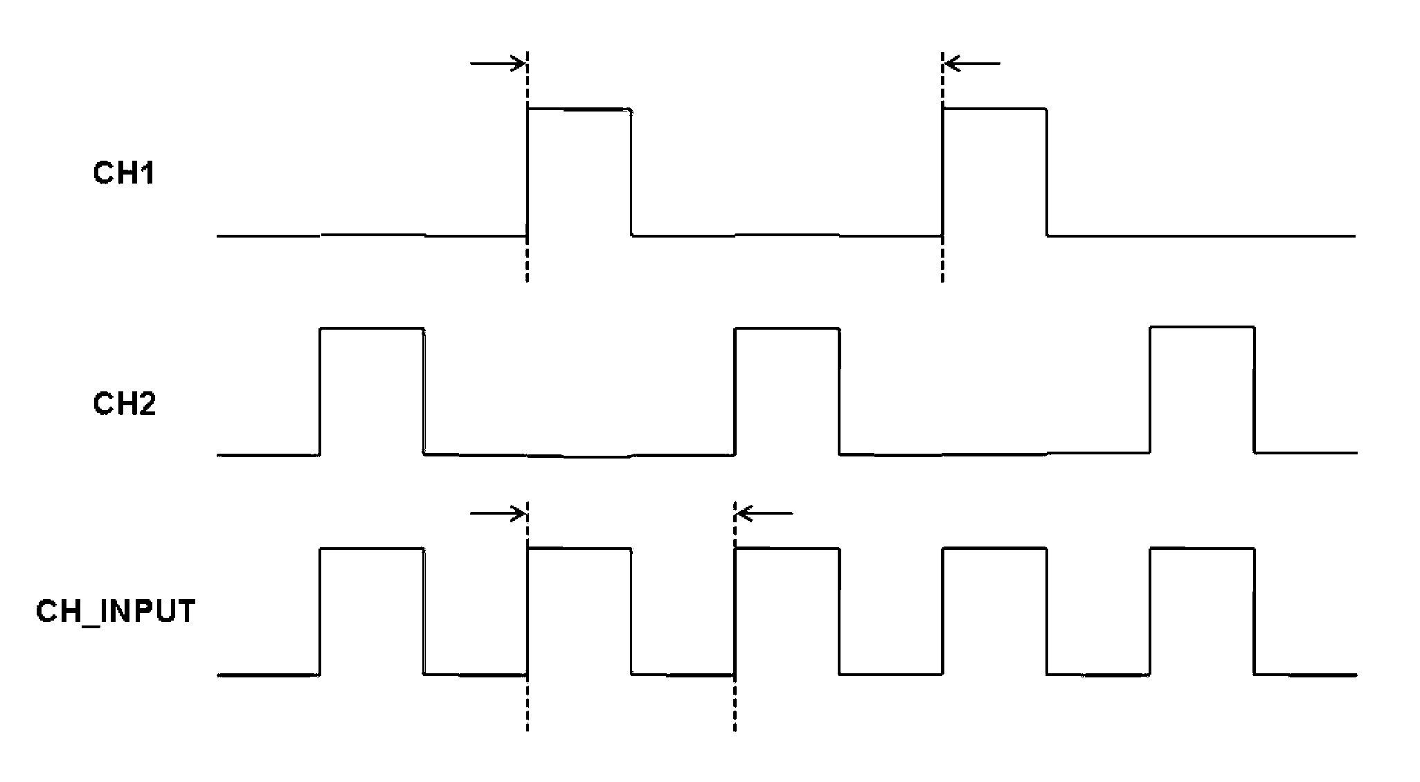
[0024] The first step: using the first output channel of the testing machine to generate the first initial test signal CH1;

[0025] The second step: use the second output channel of the testing machine to generate the second initial test signal CH2; wherein, the duration of the high level of the first initial test signal CH1 is in the duration of the low level of the second initial test signal CH2 , and the duration of the high level of the second initial test signal CH2 is within the duration of the low level of the first initial test signal CH1;

[0026] Initial test signal combining step: combine the first initial test signal CH1 and th...

no. 2 example

[0034] The first embodiment above shows the method of combining two test signals to increase the frequency of the final test signal, but obviously, the present invention can be extended to more combinations of test signals.

[0035] Therefore, the method for increasing the test signal frequency according to the second embodiment of the present invention includes:

[0036] Initial test signal generating step: using multiple output channels of the testing machine to generate multiple initial test signals respectively, wherein the duration of the high level of any one of the multiple initial test signals is in the duration of other initial test signals duration of the low level of the signal.

[0037] Initial test signal combining step: combining the multiple initial test signals to generate a final test signal, wherein, when any one of the multiple initial test signals is at a high level, the final test signal is final within the corresponding duration The test signal is high. ...

no. 3 example

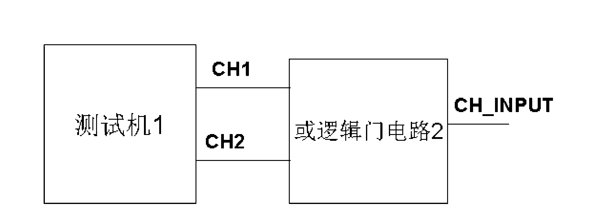
[0042] figure 2 A block diagram of a test signal generating device according to a third embodiment of the present invention is schematically shown.

[0043] Such as figure 2 As shown, the test signal generating device according to the third embodiment of the present invention includes:

[0044] The testing machine 1 is used to generate a first initial test signal CH1 and a second initial test signal CH2 on the first output channel and the second output channel respectively; wherein, the duration of the high level of the first initial test signal CH1 is at the second During the duration of the low level of the initial test signal CH2, and the duration of the high level of the second initial test signal CH2 is within the duration of the low level of the first initial test signal CH1;

[0045] OR logic gate circuit 2, its two input terminals are respectively connected to the first initial test signal CH1 and the second initial test signal CH2, and its output terminal outputs ...


PUM


Abstract

The invention provides a method for increasing testing signal frequency and testing signal generation equipment. The method for increasing the testing signal frequency comprises the following steps: 1, generating a first primary testing signal by using a first output channel of a testing machine; 2, generating a second primary testing signal by using a second output channel of the testing machine, wherein the duration of the high level of the first primary testing signal is within that of the low level of the second primary testing signal, and the duration of the high-level of the second primary testing signal is within that of the low level of the first primary testing signal; and a combination step of the primary testing signals, comprising combining the first primary testing signal and the second primary testing signal to generate a final testing signal, wherein when one of the first primary testing signal and the second primary testing signal is at the high level, and the final testing signal is at the high level during the corresponding duration.

Description

technical field [0001] The invention relates to the field of signal testing, and more specifically, the invention relates to a method for increasing the frequency of a test signal and a test signal generating device. Background technique [0002] During chip or circuit testing, test signals need to be generated. Specifically, for example, the test signal includes a clock signal for timing, and the clock signal is generally a square wave signal. [0003] Moreover, during testing of a chip or a circuit, for a chip or a circuit with a high operating frequency, a clock signal with a relatively high clock frequency needs to be generated for timing. However, the highest frequency of the square wave generated by the testing machine is limited. Generally, testing machines have the highest output frequency, such as 50M. [0004] When it is necessary to generate a square wave signal higher than the highest output frequency (for example, 50M), if the testing machine is not improved,...

Claims


Application Information

Patent Timeline
Patent Type & Authority Applications(China)
IPC IPC(8): G01R31/28G01R1/28
Inventor 王磊
Owner SHANGHAI HUAHONG GRACE SEMICON MFG CORP
Why Eureka
Try Eureka