Automobile steel plate spring stiffness checking method
A technology of leaf springs and spring stiffness, applied in the field of checking the stiffness of automobile leaf springs, can solve problems such as non-proportionality, large deviation between leaf spring stiffness and actual stiffness, and inability to meet design requirements, so as to save test costs and improve development efficiency. Effect
- Summary
- Abstract
- Description
- Claims
- Application Information
AI Technical Summary
Problems solved by technology
Method used
Image

Examples
Embodiment Construction
[0016] The present invention will be described in further detail below by way of examples.
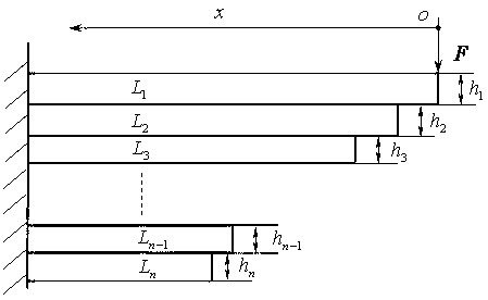
[0017] Stiffness requirements of a truck suspension leaf spring . The width of each leaf spring b =40mm; the length and thickness of each piece are as follows: L 1 =1400mm, h 1 =15mm; L 2 =1300mm, h 2 =15mm; L 3 =1200mm, h 3 =15mm; L 4 =1100mm, h 4 =12mm; L 5 =1000mm, h 5 =10mm. Modulus of elasticity of the leaf spring material Pa.
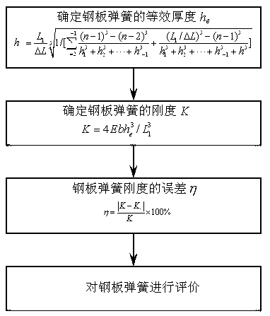
[0018] The method for checking the stiffness of the automobile leaf spring provided by the embodiment of the present invention, the calculation flow chart is as follows figure 2 As shown, the specific steps are as follows:
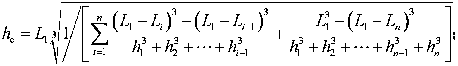
[0019] (1) According to the length and thickness of each leaf spring, that is L 1 =1400mm, h 1 =15mm; L 2 =1300mm, h 2 =15mm; L 3 =1200mm, h 3 =15mm; L 4 =1100mm, h 4 =12mm; L 5 =1000mm, h 5 =10mm to determine the equivalent thickness of the leaf spring h e for
[0020] =23.4185mm; ...
PUM
 Abstract
Description
Claims
Application Information