Eureka AIR delivers breakthrough ideas for toughest innovation challenges, trusted by R&D personnel around the world.

Cassegrain metamaterial antenna

A technology of metamaterials and antennas, applied in the field of communication, can solve the problems of difficult processing and high cost of Cassegrain antennas

Active Publication Date: 2012-11-28
KUANG CHI INST OF ADVANCED TECH
View PDF2 Cites 15 Cited by
  • Summary
  • Abstract
  • Description
  • Claims
  • Application Information

AI Technical Summary

Problems solved by technology

[0004] The technical problem to be solved by the present invention is to provide a Cassegrain-type metamaterial antenna with simple processing and low manufacturing cost for the existing Cassegrain antennas that are difficult to process and high in cost

Method used


Image

  • Cassegrain metamaterial antenna
  • Cassegrain metamaterial antenna
  • Cassegrain metamaterial antenna

Examples


Embodiment Construction

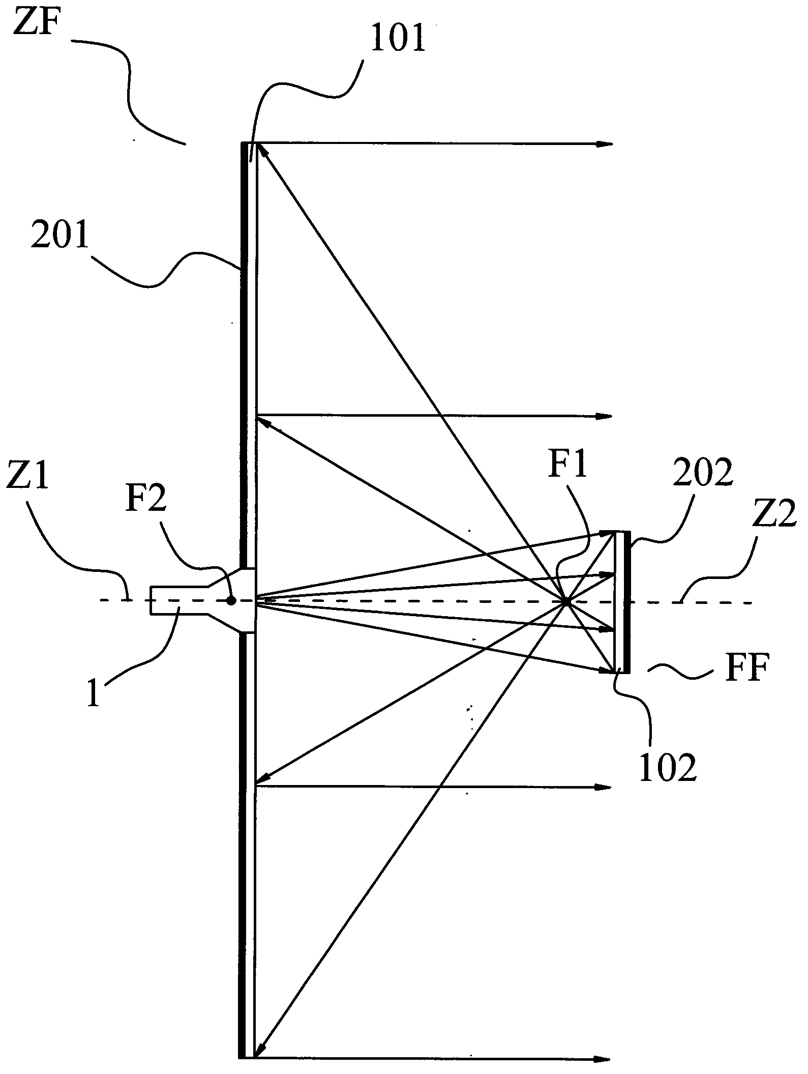
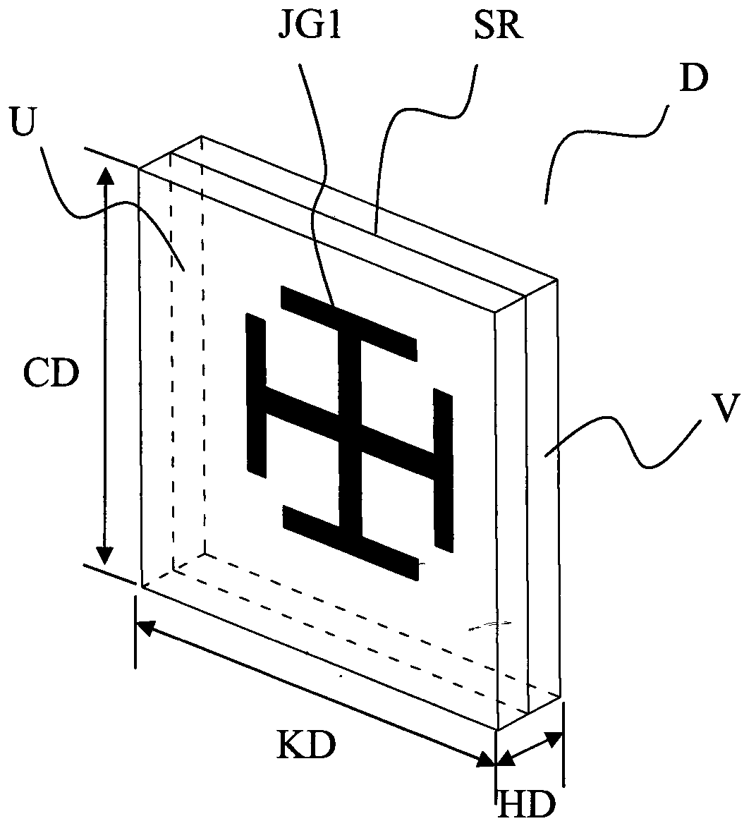
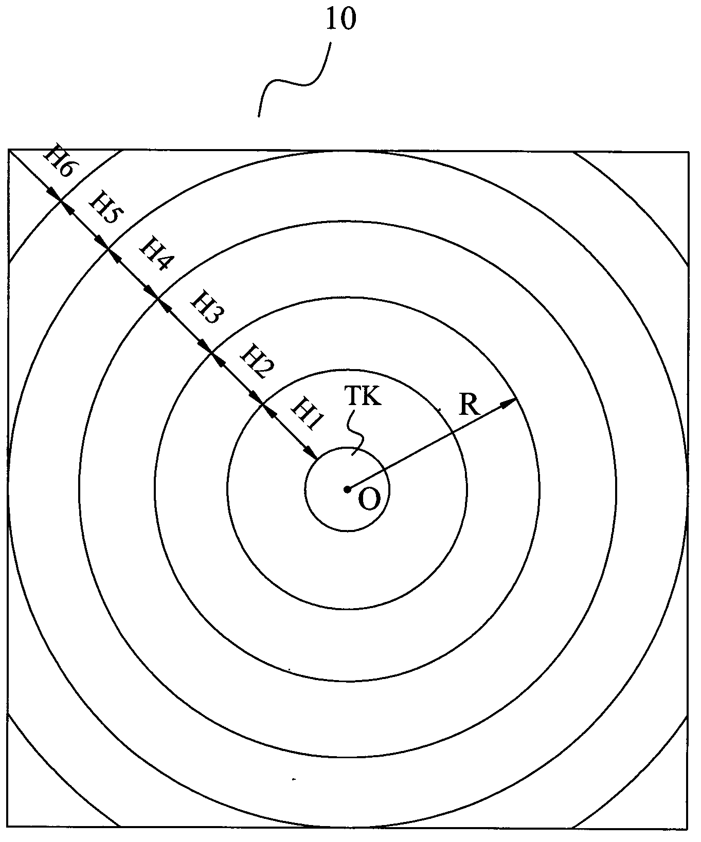
[0048] Such as Figures 1 to 4As shown, the Cassegrain type metamaterial antenna according to the present invention includes a metamaterial main reflector ZF with a central through hole TK, a feed source 1 arranged in the central through hole TK and a metamaterial secondary reflector arranged in front of the feed source 1 The electromagnetic waves radiated by the reflector FF and the feed source 1 are emitted in the form of plane waves after being reflected by the metamaterial sub-reflector FF and the metamaterial main reflector ZF in turn. The metamaterial main reflector ZF includes a first core layer 101 and a set The first reflective layer 201 on the rear surface of the first core layer 101, the first core layer 101 includes at least one first core layer sheet 10, and the first core layer sheet 10 includes a first base material JC1 and a set A plurality of first artificial microstructures JG1 on the first substrate JC1, the metamaterial sub-reflector FF includes a second co...


PUM

PropertyMeasurementUnit
Thicknessaaaaaaaaaa
Thicknessaaaaaaaaaa
Thicknessaaaaaaaaaa

Abstract

The invention discloses a Cassegrain metamaterial antenna, which comprises a main metamaterial reflector with a central through hole, a feed source arranged in the central through hole, and a secondary metamaterial reflector arranged in front of the feed source, wherein electromagnetic waves radiated by the feed source are sequentially reflected by the secondary metamaterial reflector and the main metamaterial reflector and then are emitted in a plane wave form; the secondary metamaterial reflector has electromagnetic wave reflection characteristics similar to a rotating ellipsoid; the secondary metamaterial reflector has a near focus and a far focus; the far focus is superposed with the phase center of the feed source; and the near focus is superposed with the focus of the main metamaterial reflector. According to the Cassegrain metamaterial antenna, the conventional paraboloid is replaced by the platy main metamaterial reflector, so that the Cassegrain metamaterial antenna is easier to manufacture and process and lower in cost.

Description

technical field [0001] The invention relates to the communication field, and more specifically, relates to a Cassegrain-type metamaterial antenna. Background technique [0002] The Cassegrain antenna consists of three parts, namely the main reflector, sub-reflector and radiation source. Wherein the main reflector is a rotating paraboloid, and the secondary reflecting surface is a rotating hyperboloid reflector. Structurally, one focus of the hyperboloid coincides with the focus of the paraboloid, the focal axis of the hyperboloid coincides with the focal axis of the paraboloid, and the radiation source is located at the other focus of the hyperboloid. The electromagnetic wave emitted by the radiation source is reflected by the sub-reflector once, and the electromagnetic wave is reflected to the main reflector, and then the plane wave beam in the corresponding direction is obtained after being reflected by the main reflector, so as to realize directional emission. [0003] ...

Claims


Application Information

Patent Timeline
IPC IPC(8): H01Q19/185H01Q19/06H01Q15/02H01Q15/23
Inventor 刘若鹏季春霖岳玉涛杨青殷俊
Owner KUANG CHI INST OF ADVANCED TECH
Why Eureka
Eureka Blog
Learn More