
Substrate carrying control method and substrate carrying control device for part assembly line

A substrate handling and control method technology, applied in the direction of electrical components, electrical components, etc., can solve problems such as difficult substrates, high cost, stop, etc., and achieve the effect of simple device structure and control logic, and low cost

Active Publication Date: 2012-11-28
FUJI KK
View PDF6 Cites 2 Cited by
  • Summary
  • Abstract
  • Description
  • Claims
  • Application Information

AI Technical Summary

Problems solved by technology

However, this method does not correspond to the case where the mounted part protrudes from the end of the substrate
It is difficult to accurately detect the original substrate end only by using the diffused light and the convergent light separately when considering that the type of part, the overhang (overlength), and the overhang width vary depending on the type of substrate to be produced. department
Therefore, it is difficult to accurately stop the substrate at a predetermined position
Furthermore, the method of Patent Document 1 requires a plurality of types of sensors and their selective control mechanism, which has the problem of high cost.

Method used


Image

  • Substrate carrying control method and substrate carrying control device for part assembly line
  • Substrate carrying control method and substrate carrying control device for part assembly line
  • Substrate carrying control method and substrate carrying control device for part assembly line

Examples


Embodiment Construction

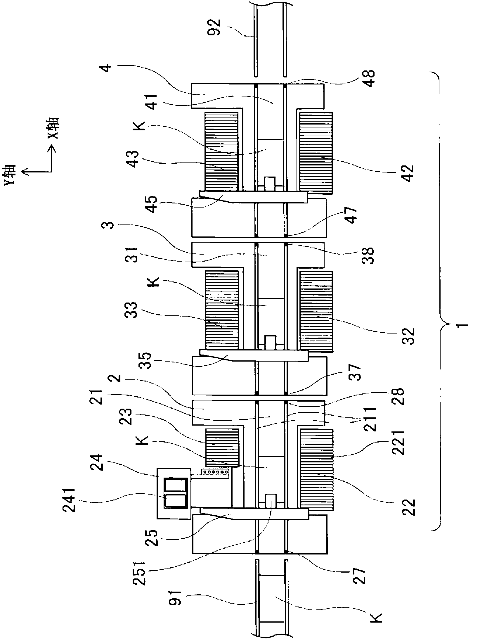
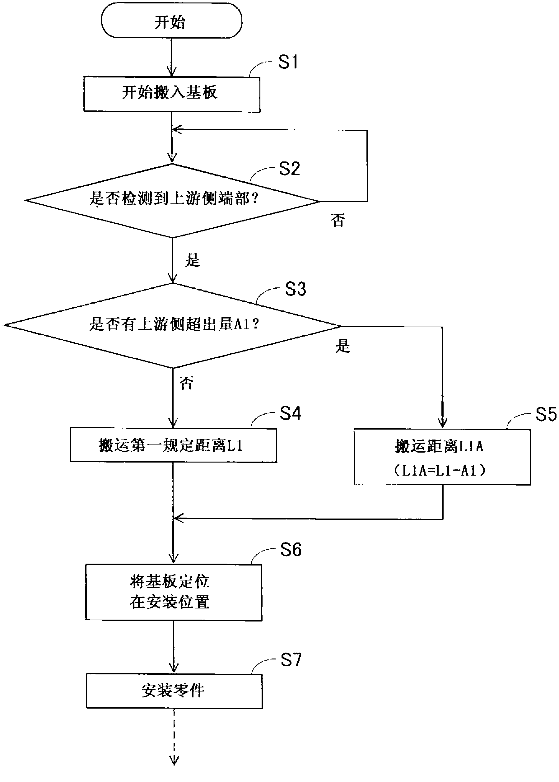
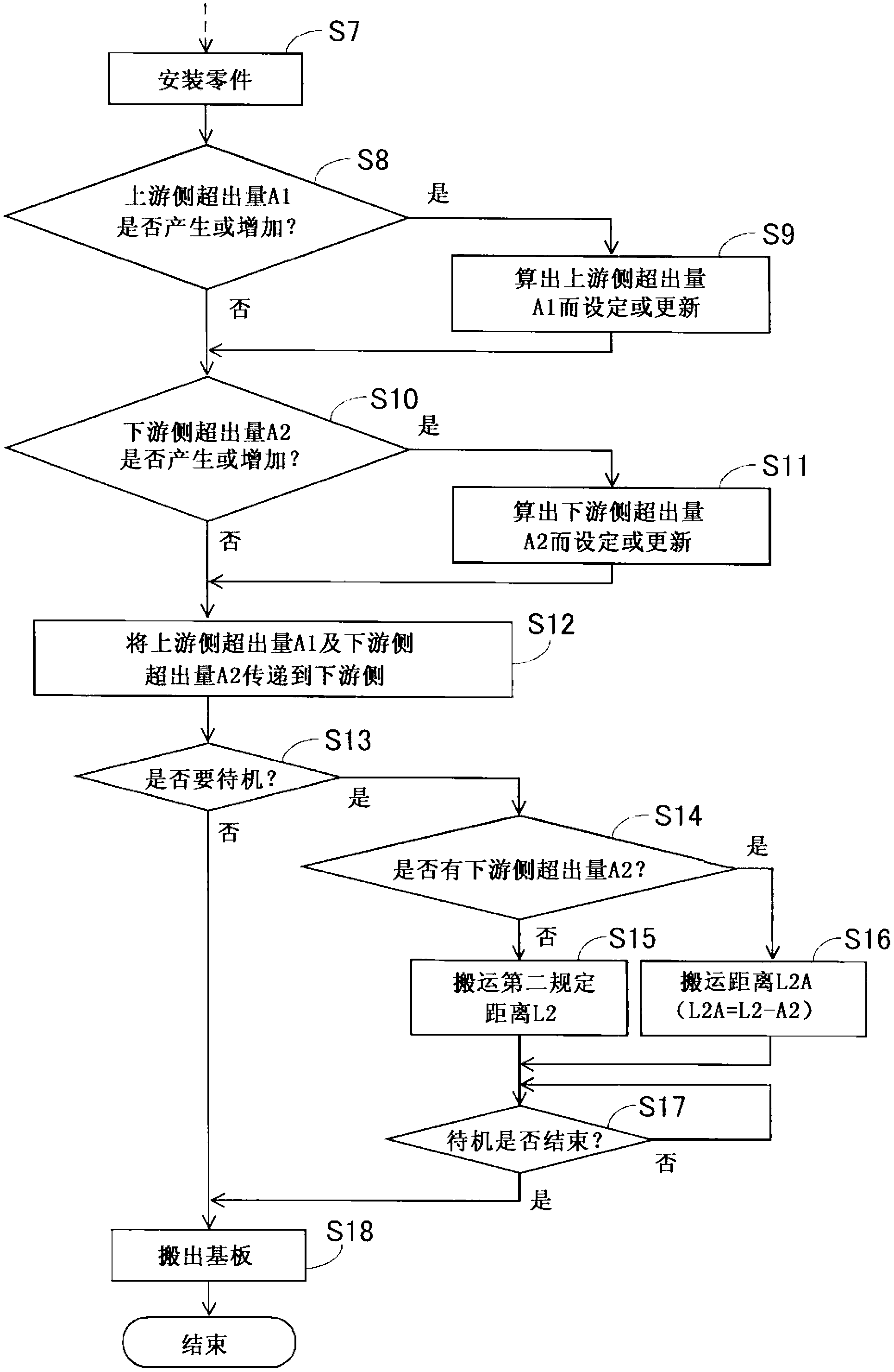
[0047] refer to Figure 1~Figure 5 , a method for controlling substrate transportation in a component mounting line according to an embodiment of the present invention will be described. figure 1 It is a top view explaining the structural example of the component mounting line 1 which implements the board|substrate conveyance control method of embodiment. A parts mounting line 1 for performing a mounting process is configured by arranging three parts mounting machines 2 to 4 in series. On the upstream side of part mounting line 1 ( figure 1 The left side of ) is arranged a board transfer device 91 that carries in a board K that has completed a printing process from a solder printing machine not shown in the figure. Also, on the downstream side of the parts mounting line 1 ( figure 1 The right side of the substrate) is disposed with a substrate transfer device 92 that transfers the substrate K that has completed the mounting process to a substrate inspection machine (not sho...


PUM


Abstract

Provided is a low-cost substrate carrying control method and a substrate carrying control device for a part assembly line, even for an overranging substrate that a part is arranged beyond an end portion of the substrate, the overranging substrate also can be accurately stopped at an assembling position and a standby position of a part assembling machine. The substrate carrying control method for the part assembly line formed by a plurality of part assembling machines which are arranged in a line comprises: an overranging amount calculating process for calculating an overranging amount when the part arranged on the substrate stopped at the assembling position is arranged beyond the end portion of the substrate in a carrying direction in the each part assembling machine; an overranging amount transmitting process for transmitting the overranging amount successively before carrying the overranging substrate successively towards the part assembling machines at a downstream side; and an overranging substrate carrying process for carrying the overranging substrate with a distance obtained by subtracting the overranging amount from a prescribed distance in the part assembling machines at a downstream side, so as to enable the overranging substrate to stop at a prescribed position.

Description

technical field [0001] The present invention relates to a substrate conveyance control method and a substrate conveyance control device of a component mounting line in which a plurality of component mounters are arranged in series, and more specifically, relates to control of a stop position beyond a substrate in which components protrude from the end of the substrate. Background technique [0002] There are solder printing machines, parts mounting machines, reflow machines, board inspection machines, etc. as board production machines that manufacture boards on which many parts are mounted, and board production lines are generally constructed by connecting them with board transfer devices. Furthermore, in many cases, a plurality of modular parts mounting machines are arranged in series to constitute a parts mounting line. The substrate transfer device plays a role of transferring substrates sequentially between these substrate production machines, and transporting the substr...

Claims


Application Information

Patent Timeline
Patent Type & Authority Applications(China)
IPC IPC(8): H05K13/02
Inventor 清水浩二原朗
Owner FUJI KK
Learn More