Heating device for flat glass

A heating device, flat glass technology, applied in glass tempering, glass production, glass manufacturing equipment and other directions, can solve the problems of increased inner cavity pressure, large energy loss, increased glass production cost, etc., and achieve the effect of reducing production cost

Active Publication Date: 2015-06-17
LUOYANG NORTHGLASS TECH +2
View PDF6 Cites 0 Cited by
  • Summary
  • Abstract
  • Description
  • Claims
  • Application Information

AI Technical Summary

Problems solved by technology

When the heating equipment is working, it takes a long time to inject cold compressed air into its inner cavity, which causes the pressure in the inner cavity to rise and has to discharge high-temperature air to the outside for a long time, which leads to excessive energy loss in the production process and the production of glass. The cost also increases

Method used


Image

  • Heating device for flat glass
  • Heating device for flat glass
  • Heating device for flat glass

Examples


Embodiment Construction

[0019] In order to better understand the shape, structure and characteristics of the present invention, preferred embodiments will be listed below and described in detail with reference to the accompanying drawings.

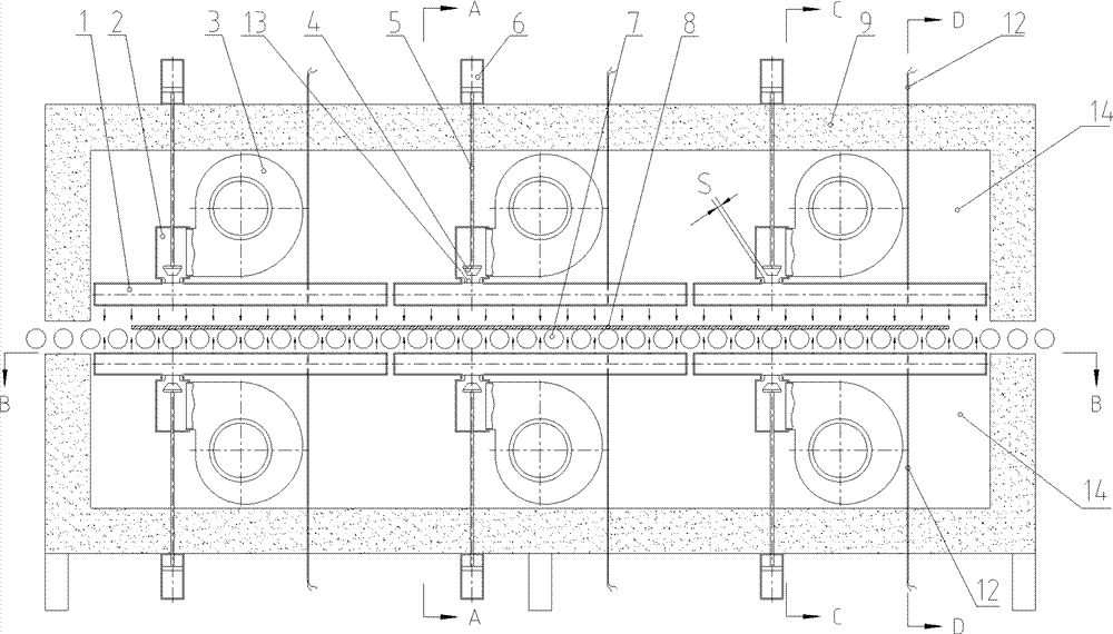
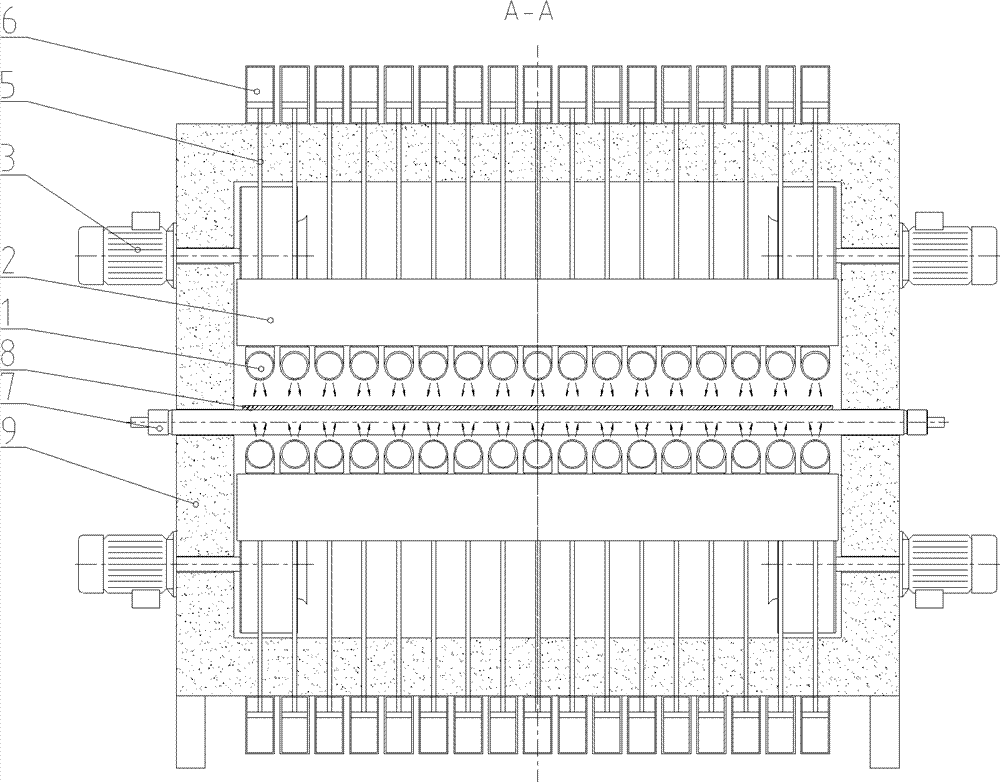
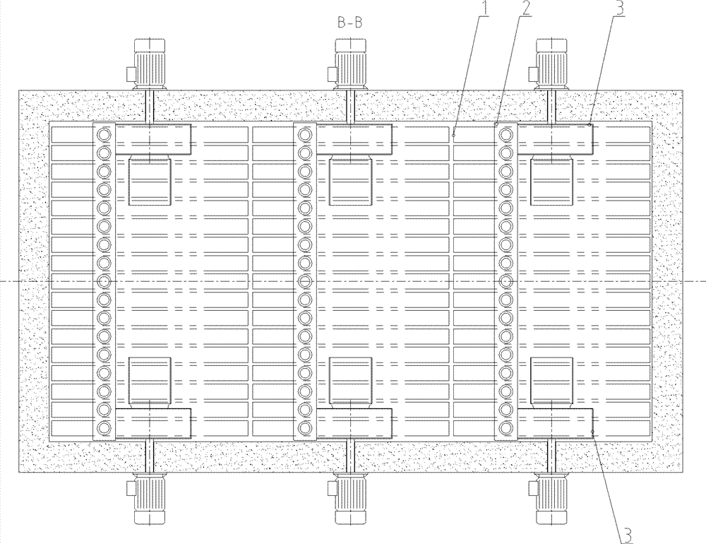
[0020] The core of the present invention is that the heating temperature inside the furnace cavity 14 is controlled by the temperature of the heater 11 arranged at the air inlet of the thermal circulation fan 3, and the temperature of each radiation convection tube 1 and the convective heating intensity to the glass 8 can be controlled by the inflow The high temperature gas flow rate (or pressure) in each tube is controlled. Each radiation convection tube 1 is arranged near the upper and lower surfaces of the glass 8 along the longitudinal direction (that is, the conveying direction of the glass), forming a continuous and uniform radiation convection belt to uniformly heat the entire upper and lower surfaces of the glass 8 .

[0021] Wherein, the high-temperature...


PUM


Abstract

The invention discloses a heating device for flat glass. Key points are that: the heating temperature inside a furnace cavity is controlled through the temperature of a heater arranged at the air inlet of a thermal circulating fan; and the temperature of each radiation-convection pipe and the convection heating strength on glass can be controlled through the magnitude of high-temperature gas flow (or pressure) in each pipe. Each radiation-convection pipe is arranged close to the upper and lower surfaces of the glass along the longitudinal direction (the conveying direction of the glass), so that a continuous and uniform radiation-convection zone is formed on a whole for performing radiation and convection heating on the entire upper and lower surfaces of the glass. Convection heating air flow is generated by the thermal circulating fan arranged inside the cavity, and an internal circulating air course is formed inside the furnace cavity, so that heat energy of the heater in a working process is transmitted to the glass surface continuously.

Description

technical field [0001] The invention relates to a heating device, in particular to a heating device for flat glass in glass tempering technology. Background technique [0002] A comparison is made for two types of heating equipment for flat glass that appear on the market. The first is that the heating element is set at the air inlet of the thermal circulation fan, and the radiation convection pipes are arranged near the upper and lower surfaces of the glass along the transverse direction (that is, perpendicular to the conveying direction of the glass), and the high-temperature airflow flowing into each radiation convection pipe The flow or pressure cannot be controlled separately, so that the temperature control in the width direction of the heating equipment cannot be carried out in different regions. For relatively large glass, the two sides are often overheated and the middle is insufficiently heated, resulting in wave deformation and bow deformation of the glass after b...

Claims


Application Information

Patent Timeline
Patent Type & Authority Patents(China)
IPC IPC(8): C03B27/012
CPCY02P40/57
Inventor 高学林白雪峰
Owner LUOYANG NORTHGLASS TECH
Why Eureka
Try Eureka