

Exhaust and silencing pipe device
A technology for muffler pipes and exhaust pipes, which is applied in the direction of muffler devices, engine components, machines/engines, etc. It can solve the problems of easy blockage of small holes, large muffler resistance, complex structure, etc., and achieve large muffler volume and safe and reliable use , the effect of simple structure
Inactive Publication Date: 2012-12-05
赵爱荣
View PDF0 Cites 0 Cited by
- Summary
- Abstract
- Description
- Claims
- Application Information
AI Technical Summary
Problems solved by technology
[0003] The purpose of the present invention is to provide an exhaust muffler pipe device with small resistance, simple structure and good noise reduction effect, which overcomes the defects of the existing mufflers such as high resistance, complex structure and easy blockage of small holes
Method used
View moreImage
Smart ImageViewing Examples

Examples
Embodiment Construction
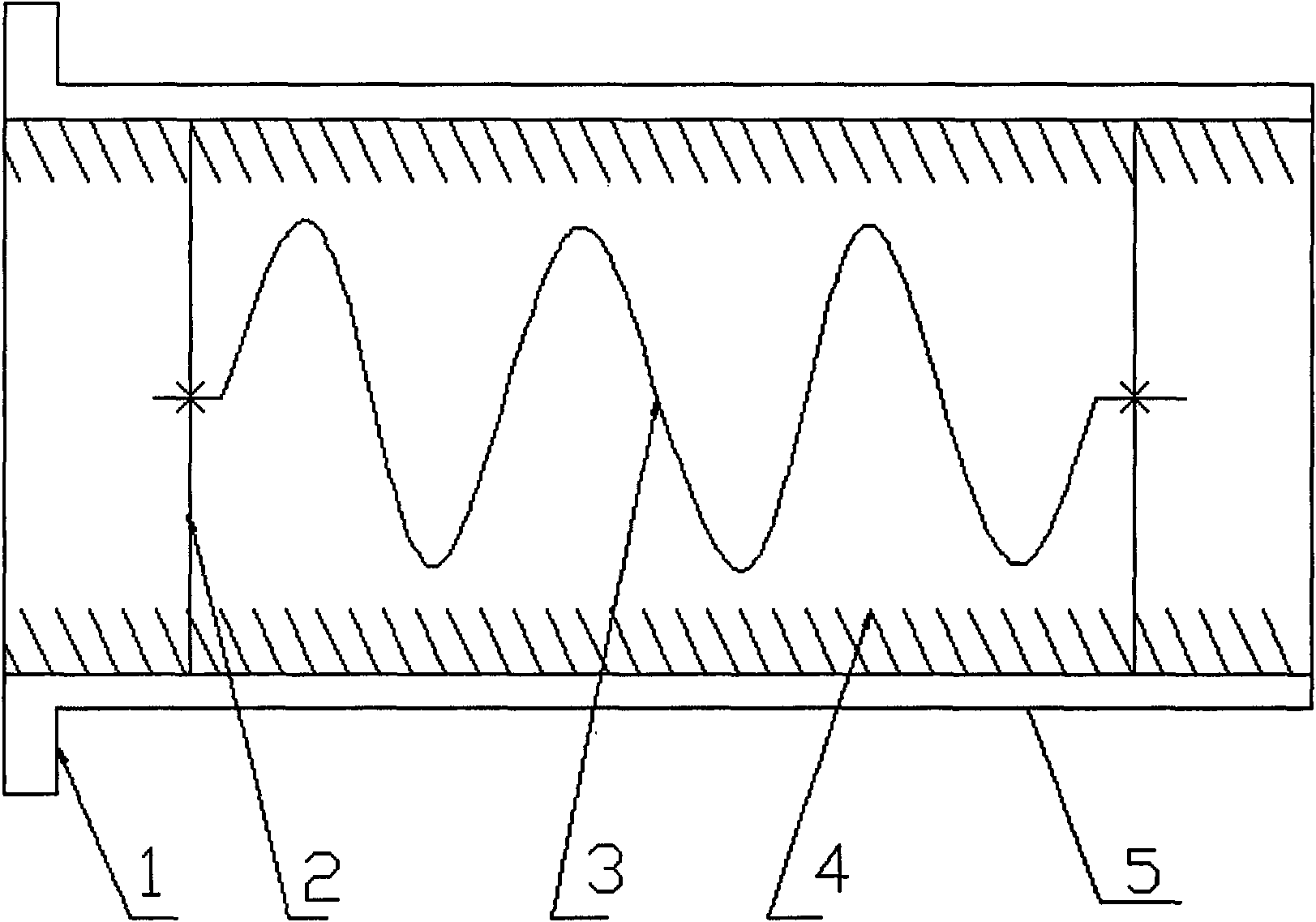
[0010] The exhaust muffler pipe has a manufactured forward spiral vane shaft (3) and reverse spiral vane barrel (4), and the outer circular surface of the reverse spiral leaf barrel (4) is installed and fixed on the exhaust pipe (1) Inside, use the bracket (2) to install the forward spiral blade shaft (3) in the middle of the exhaust pipe (1). When installing the forward spiral blade shaft (3) and the reverse spiral blade barrel (4), the two The helical direction relationship of the latter is opposite.
Login to View More PUM
 Abstract
The invention relates to an exhaust and silencing pipe device which consists of an exhaust pipe, a support frame, a positive spiral blade shaft, a reverse spiral blade barrel and a silencing pipe body; the exhaust and slicing pipe is provided with the positive spiral blade shaft and the reverse spiral blade barrel which are manufactured; the outer circle surface of the reverse spiral blade barrel is installed and fixed inside the exhaust pipe; the positive spiral blade shaft is installed at the middle part of the exhaust pipe by the support frame; and when the positive spiral blade shaft and the reverse spiral blade barrel are installed, the spiral rotation directions of the positive spiral blade shaft and the reverse spiral blade barrel are opposite.
Description
technical field [0001] The invention relates to a muffler pipe device, in particular to an exhaust muffler pipe device, which belongs to the technical field of exhaust muffler. Background technique [0002] As we all know, the noise reduction principle currently used in chemical industry, petroleum, metallurgy, electric power, automobile, boiler and other industries mainly has two aspects: throttling, decompression and small hole blocking tail. Common forms of mufflers include throttling and decompression mufflers, small-hole tail-blocking mufflers and a combination of the two. The above three types of mufflers have the following disadvantages respectively: 1, the resistance is relatively large; 2, the structure is complex; 3, the small holes are easy to block. Contents of the invention [0003] The object of the present invention is to provide an exhaust muffler pipe device with small resistance, simple structure and good noise reduction effect, which overcomes the defec...
Claims
Login to View More Application Information
Patent Timeline
 Patent Type & AuthorityApplications(China)
IPC IPC(8): F01N1/12
Inventor赵爱荣
Owner赵爱荣