Novel muffler for excavator

A muffler and excavator technology, which is applied in the direction of mufflers, machines/engines, mechanical equipment, etc., can solve the problems of unsatisfactory noise reduction effect, little difference in perforation rate, and insufficient noise reduction effect, etc., and achieves significant noise reduction effect, The effect of high working reliability and reasonable structure

Active Publication Date: 2013-01-23
SHANDONG LISHIDE MACHINERY
View PDF7 Cites 0 Cited by
  • Summary
  • Abstract
  • Description
  • Claims
  • Application Information

AI Technical Summary

Problems solved by technology

[0002] At present, most of the practical hydraulic excavator mufflers on the market have a 3-cavity structure, the number of cavities is limited, the perforation rate is not much different, the noise reduction effect is slightly insufficient, and the noise reduction effect is not ideal

Method used


Image

  • Novel muffler for excavator
  • Novel muffler for excavator
  • Novel muffler for excavator

Examples


Embodiment Construction

[0019] Below in conjunction with accompanying drawing, the present invention will be further described:

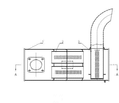
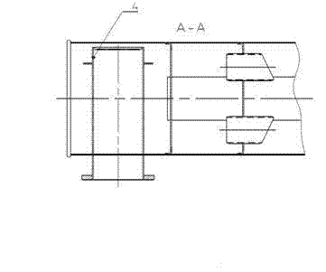
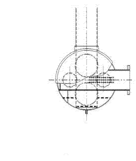
[0020] The air exhausted by the engine passes through the muffler I (see attached Figure 7 ) into the first chamber of the muffler, the first-stage perforated pipe is used for preliminary noise reduction and silencer, and then enters into the front chamber of the muffler barrel II respectively (see attached Figure 4 ), the upper and lower mufflers (2) of the muffler, that is, the left expansion chamber, after noise reduction and muffler, enter the rear chamber of the muffler II through the inner tubes (4) on both sides, that is, the right expansion chamber, After passing through the upper and lower two mufflers (2) for noise reduction and silencer, it enters the muffler III, and after the perforation passes through the muffler III for the last noise reduction and muffler, it is discharged from the exhaust tailpipe. After the muffler of the present invention is optimized ...


PUM


Abstract

The invention discloses a muffler for an excavator. The muffler comprises a shell which encircles a muffling tube I, a muffling tube II and a muffling tube III, wherein the middle of the muffling tube II is partitioned into two cavities, namely a front cavity and a rear cavity, by a partition board; each of the two cavities is partitioned into two parts, namely an upper part and a lower part; the two cavities are communicated with each other by adopting an inner insertion pipe; the inner insertion pipe is designed as a diagonal slope; and the punching rates of the muffling tube I, the muffling tube II and the muffling tube III are between 8.9% and16.4% and are increased sequentially, i.e., the punching rate of the muffling tube III is larger than that of the rear cavity of the muffling tube II, the punching rate of the rear cavity of the muffling tube II is larger than that of the front cavity of the muffling tube II, and the punching rate of the front cavity of the muffling tube II is larger than that of the muffling tube I. By fully using the toning function of a punching pipe, the muffling performance of a frequency band can be improved; a slope design of the inner insertion pipe is adopted, so that the distribution of flow fields is improved; and simultaneously, a certain muffling effect can be achieved.

Description

technical field [0001] The invention relates to a muffler for an excavator, which belongs to the field of engineering machinery. Background technique [0002] At present, most of the practical hydraulic excavator mufflers on the market have a 3-cavity structure, the number of cavities is limited, the perforation rate is not much different, the noise reduction effect is slightly insufficient, and the noise reduction effect is not ideal. Contents of the invention [0003] In order to improve the noise reduction effect of the muffler, we invented a muffler for excavators, which includes a housing, the housing surrounds the muffler I, the muffler II, and the muffler III, wherein the muffler II The middle of the chamber is divided into front and rear two chambers by a partition, and the two chambers are divided into upper and lower parts. The two chambers are connected by an internal intubation tube. The internal intubation tube is designed in the form of an oblique groove. Th...

Claims


Application Information

Patent Timeline
Patent Type & Authority Patents(China)
IPC IPC(8): F01N13/00
Inventor 季辉石岩宋祥献许跃雷王振华公维水李永刚王经聪史继松王维磊
Owner SHANDONG LISHIDE MACHINERY
Why Eureka
Try Eureka