Display apparatus

A display device, image display device technology, applied in static indicators, image data processing, optics, etc., can solve the problem that the image is not given a sufficient high contrast, achieve high contrast and reduce power consumption

Active Publication Date: 2012-12-05
SONY CORP
View PDF23 Cites 65 Cited by
  • Summary
  • Abstract
  • Description
  • Claims
  • Application Information

AI Technical Summary

Problems solved by technology

[0008] However, in the case where the surrounding environment where the image display device 100' or 300' is located is very bright, or depending on the content of the displayed image, there may be a problem that the image viewed by the observer is not given a sufficiently high contrast.

Method used


Image

  • Display apparatus
  • Display apparatus
  • Display apparatus

Examples


no. 1 example

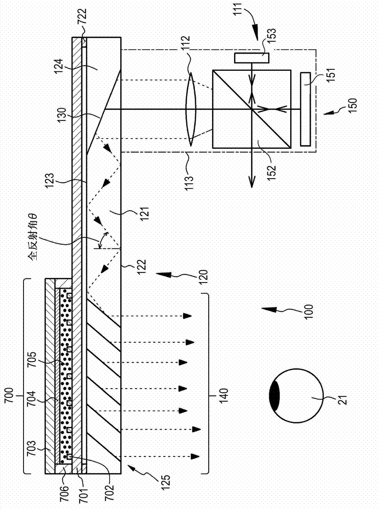
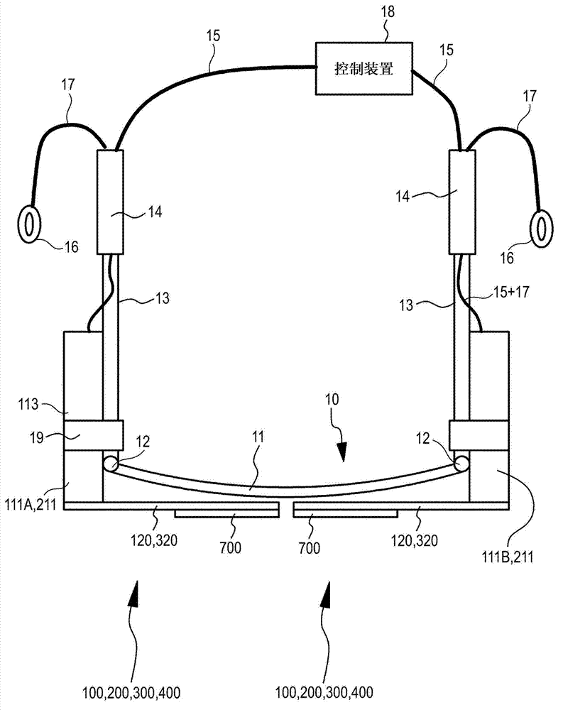
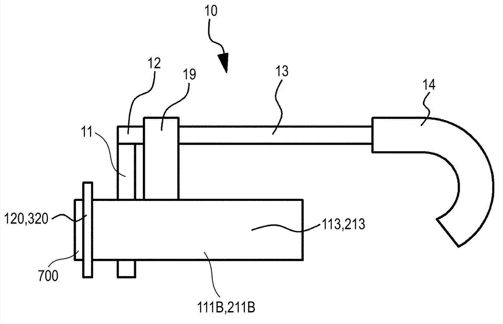
[0187] The first example relates to the display device according to the first embodiment of the present disclosure. figure 1 is a conceptual diagram showing the image display device according to the first embodiment. figure 2 is a schematic diagram showing the display device (specifically, a head-mounted display (HMD)) according to the first embodiment viewed from the upper side. Figure 3A is a schematic diagram showing a display device viewed from the side, Figure 3B is a schematic diagram showing the optical device and the light control device of the display device viewed from the front side. Figure 4A and Figure 4B is a schematic cross-sectional view showing the action of the light control device of the display device according to the first embodiment.

[0188] The image display devices 100 , 200 , 300 , 400 , and 500 according to the first embodiment or the second to eighth embodiments to be described below include (A) image forming devices 111 and 211 and (B) optic...

no. 2 example

[0226] The second embodiment is a modification of the first embodiment. Figure 5 is a conceptual diagram showing an image display device 200 of a display device (head-mounted display) according to the second embodiment. like Figure 5 As shown, in the second embodiment, the image forming apparatus 211 is an image forming apparatus according to the second configuration. That is, the image forming device 211 includes a light source 251 and a scanning unit 253 that performs scanning with parallel light emitted from the light source 251 . Specifically, the image forming device 211 includes: (i) a light source 251; (ii) a collimating optical system 252 that converts light emitted from the light source 251 into parallel light; (iii) uses the parallel light emitted from the collimating optical system 252 to a scanning unit 253 that performs scanning; and (iv) a relay optical system 254 that transmits parallel light used by the scanning unit 253 to perform scanning. in housing 213...

no. 3 example

[0230] The third embodiment is also a modification of the first embodiment. Image 6 is a conceptual diagram showing an image display device 300 of a display device (head-mounted display) according to the third embodiment. Figure 7 is an enlarged cross-sectional view schematically showing a part of a reflective volume hologram diffraction grating. In the third embodiment, an image forming apparatus 111 is an image forming apparatus according to the first configuration, similarly to the first embodiment. The optical device 320 has the same basic configuration and structure as the optical device 120 according to the first embodiment, except for the configuration and structure of the first deflection unit and the second deflection unit.

[0231] In the third embodiment, a first deflection unit and a second deflection unit are disposed on the surface of the light guide plate 321 (specifically, the second surface 323 of the light guide plate 321 ). The first deflection unit diff...


PUM

PropertyMeasurementUnit
thicknessaaaaaaaaaa
densityaaaaaaaaaa
densityaaaaaaaaaa

Abstract

A display apparatus includes: (i) a glasses-type frame that is mounted on the head of an observer; and (ii) an image display device that is attached to the frame, wherein the image display device includes (A) an image forming device, and (B) an optical device on which light emitted from the image forming device is incident, in which the light is guided, and from which the light is emitted, a light control device that adjusts an amount of external light incident from the outside is provided in a region of the optical device from which light is emitted, and the light control device includes two opposite transparent substrates, electrodes that are provided on the substrates, and an electrophoretic dispersion liquid that is sealed between the two substrates.

Description

technical field [0001] The present disclosure relates to a display device, and more particularly, to a display device using a head mounted display (HMD: head mounted display). Background technique [0002] In recent years, augmented reality (AR: augmented reality) technology that combines virtual objects or various types of information as additional information into electronic information about the real environment (or a part thereof) and presents the combined information . To implement such augmented reality technology, for example, head-mounted displays have been studied as devices for presenting visual information. In addition, head-mounted displays are expected to be used for work support in real environments. For example, a head mounted display may be used to provide road guidance information and provide technical information to an engineer performing maintenance, for example. In particular, the head-mounted display is very convenient since the hands are not occupied...

Claims


Application Information

Patent Timeline
Patent Type & Authority Applications(China)
IPC IPC(8): G02B27/01G02F1/167
CPCG02B27/0172G02F1/167G02B6/005G02F1/133524G02F2201/44G02B27/0176G02B2027/0118G02B2027/0178G06T19/006G09G3/3406G09G3/344G09G2360/144
Inventor 町田晓夫高桥贤一高梨英彦铃木谦治
Owner SONY CORP
Why Eureka
Try Eureka