Electric mechanism riveting mould

An electrical and riveting technology, used in forming tools, manufacturing tools, metal processing equipment, etc., can solve the problems of long riveting time, increased labor cost, poor consistency and standardization of operating procedures, etc., to reduce labor The cost of expenditure, the effect of saving production time

Inactive Publication Date: 2012-12-12
SUZHOU DELLFLY ELECTRONICS
View PDF7 Cites 4 Cited by
  • Summary
  • Abstract
  • Description
  • Claims
  • Application Information

AI Technical Summary

Problems solved by technology

[0002] as attached figure 1 As shown in the electrical mechanism, after the electrical mechanism 1 assembles the four connecting shafts 2 on it, the two ends of the connecting shafts 2 need to be riveted respectively. Each riveting point is riveted sequentially, which not only takes a long time for riveting and increases the cost of manpower, but also often directly affects the processing quality of the product due to poor consistency and standardization of operating procedures.

Method used


Image

  • Electric mechanism riveting mould
  • Electric mechanism riveting mould
  • Electric mechanism riveting mould

Examples


Embodiment Construction

[0015] The present invention is described below in conjunction with accompanying drawing.

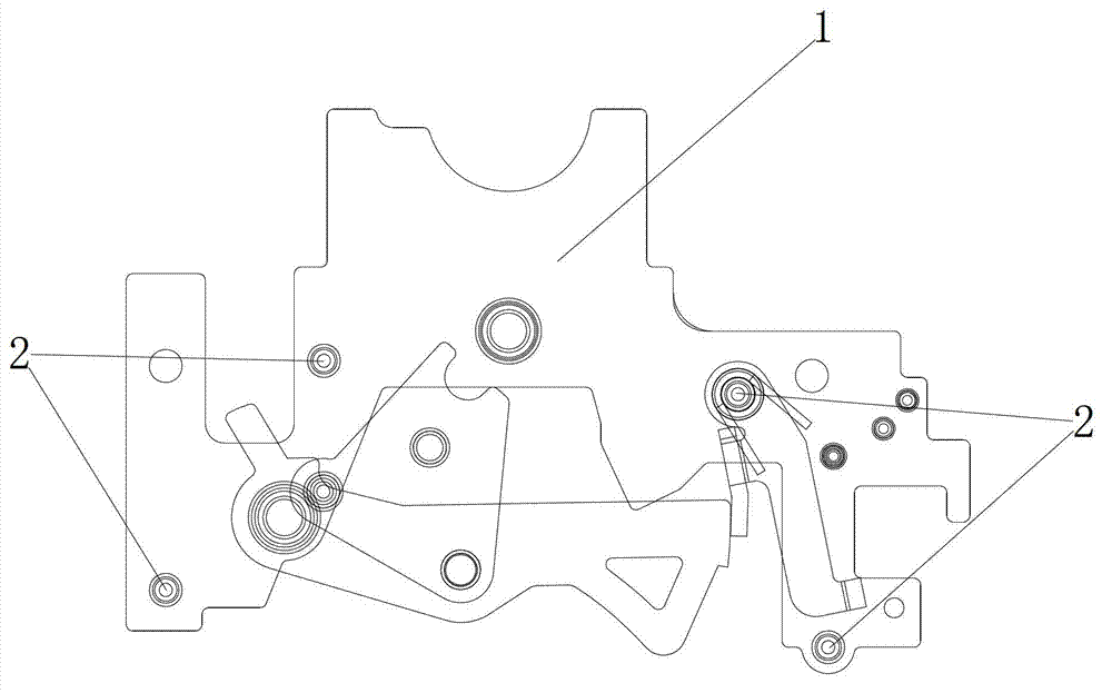
[0016] attached figure 1 It is a structural schematic diagram of an electric mechanism in the prior art, which has four connecting shafts 2, and the shaft ends of the connecting shafts 2 are connected to the electric mechanism 1 by riveting.

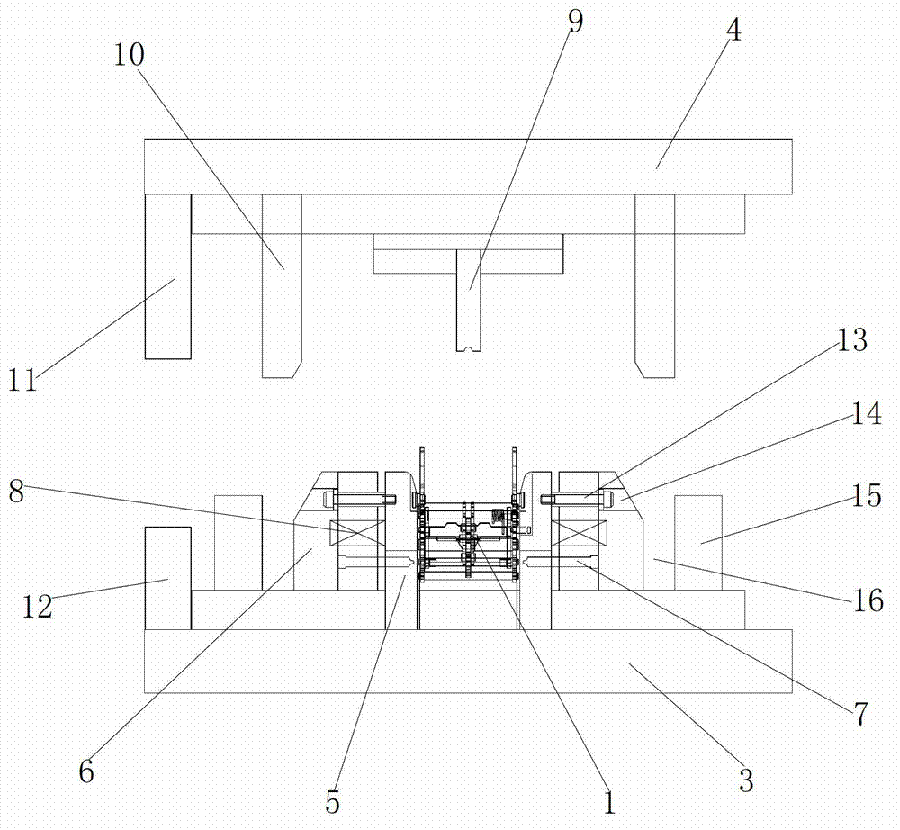
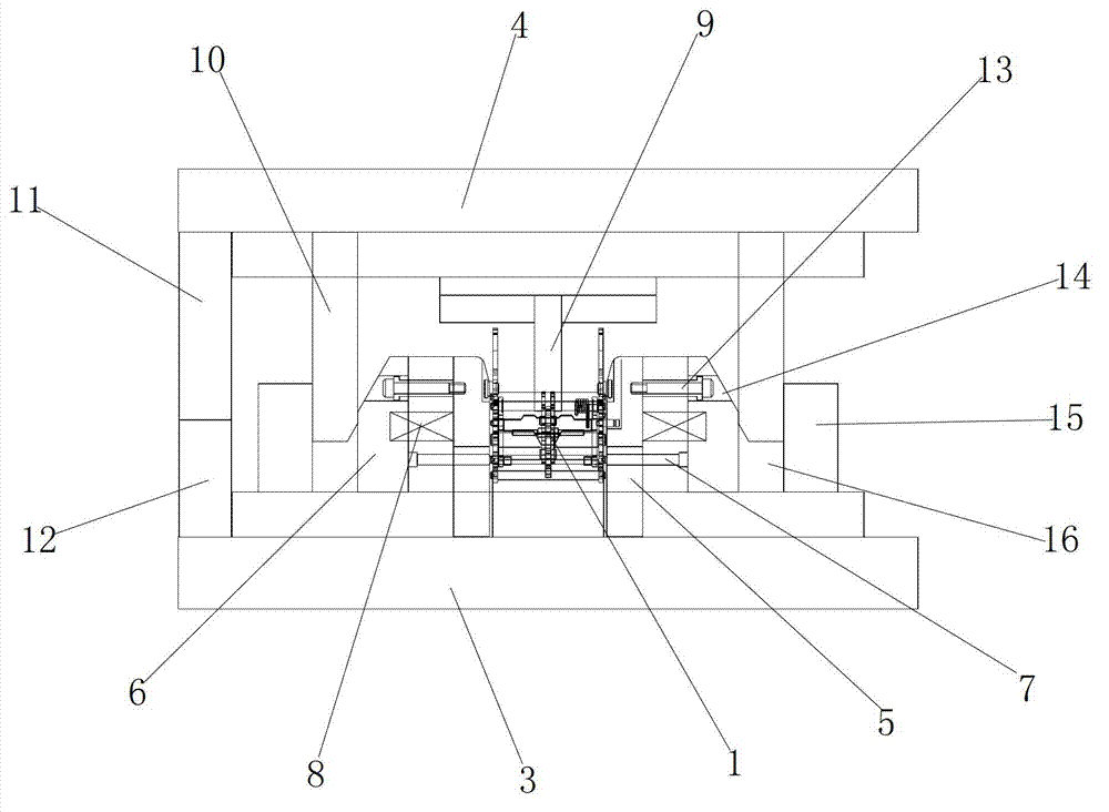
[0017] attached figure 2 , 3 It is a kind of electric mechanism riveting die described in the present invention, comprises bottom mold base 3 and the upper mold base 4 used in conjunction with it; Bottom mold base 3 is provided with electric mechanism positioning block 5, and electric mechanism positioning block 5 has four groups , which are respectively vertical plate-shaped bodies and in a rectangular array on the middle part of the bottom mold base 3, the electrical mechanism 1 is installed on the four sets of electrical mechanism positioning blocks 5, and the two sets of electrical mechanism positioning blocks 5 on the opposite side are res...


PUM


Abstract

The invention discloses an electric mechanism riveting mould comprising a bottom mould seat and an upper mould seat which is matched with the bottom mould seat; both sides of the bottom mould seat are respectively provided with electric mechanism positioning blocks and mobile push blocks sequentially and symmetrically; springs are arranged between the electric mechanism positioning blocks and the mobile push blocks; a plurality of stamping nails are arranged on the inner end surfaces of the mobile push blocks; the stamping nails extend towards the direction of the electric mechanism; the upper mould seat is provided with a pressure block and slotting tools which extend towards the bottom mould seat vertically; and the slotting tools are arranged on both sides of the pressure block and can horizontally move along the upper mould seat. According to the scheme of the invention, the electric mechanism needing to be riveted is arranged between the electric mechanism positioning blocks on the left side and the right side of the bottom mould seat, the upper mould seat is lowered, the pressure block presses the electric mechanism, the slotting tools push the mobile push blocks on both sides, the mobile push blocks respectively push the stamping nails to the position of the electric mechanism needing to be riveted to rivet, so that the riveting of a plurality of points of the electric mechanism can be completed in only one step, not only is the manufacturing time greatly saved, but also the expenditure of manpower cost is reduced.

Description

technical field [0001] The invention relates to a mold, in particular to an electric mechanism riveting mold. Background technique [0002] as attached figure 1 As shown in the electrical mechanism, after the electrical mechanism 1 assembles the four connecting shafts 2 on it, the two ends of the connecting shaft 2 need to be riveted respectively. In the prior art, the operator usually holds the product on the riveting machine for eight Each riveting point is riveted sequentially, which not only takes a long time for riveting and increases the cost of manpower, but also often directly affects the processing quality of the product due to poor consistency and standardization of operating procedures. Contents of the invention [0003] In view of the above-mentioned technical problems, the object of the present invention is to propose a riveting die for an electric mechanism with simple structure and reliable performance. The riveting die for the electric mechanism only needs...

Claims


Application Information

Patent Timeline
Patent Type & Authority Applications(China)
IPC IPC(8): B21D37/10
Inventor 邱惠新
Owner SUZHOU DELLFLY ELECTRONICS
Why Eureka
Try Eureka