
Full-automatic pipe cutting machine

A fully automatic, cutting machine technology, applied in metal sawing equipment, sawing machine equipment, metal processing equipment, etc., can solve the problems of low cutting efficiency, low cutting accuracy, and large labor, and achieve high cutting efficiency and labor. Small, labor-intensive effect

Active Publication Date: 2012-12-12
冠达星股份有限公司
View PDF7 Cites 65 Cited by
  • Summary
  • Abstract
  • Description
  • Claims
  • Application Information

AI Technical Summary

Problems solved by technology

[0002] In actual production engineering, it is often necessary to cut long pipes into several sections according to actual needs. The cutting of pipes is completed on a cutting machine. The existing cutting machine usually only has one cutting circular saw blade. Multi-sections require multiple cuts, and multiple measurements of the cutting length are required to cut out a pipe section with a specific length. In addition, the above-mentioned cutting processes are all manually operated, which not only causes disadvantages such as low cutting efficiency, heavy labor, and low cutting accuracy.

Method used


Image

  • Full-automatic pipe cutting machine
  • Full-automatic pipe cutting machine
  • Full-automatic pipe cutting machine

Examples


Embodiment Construction

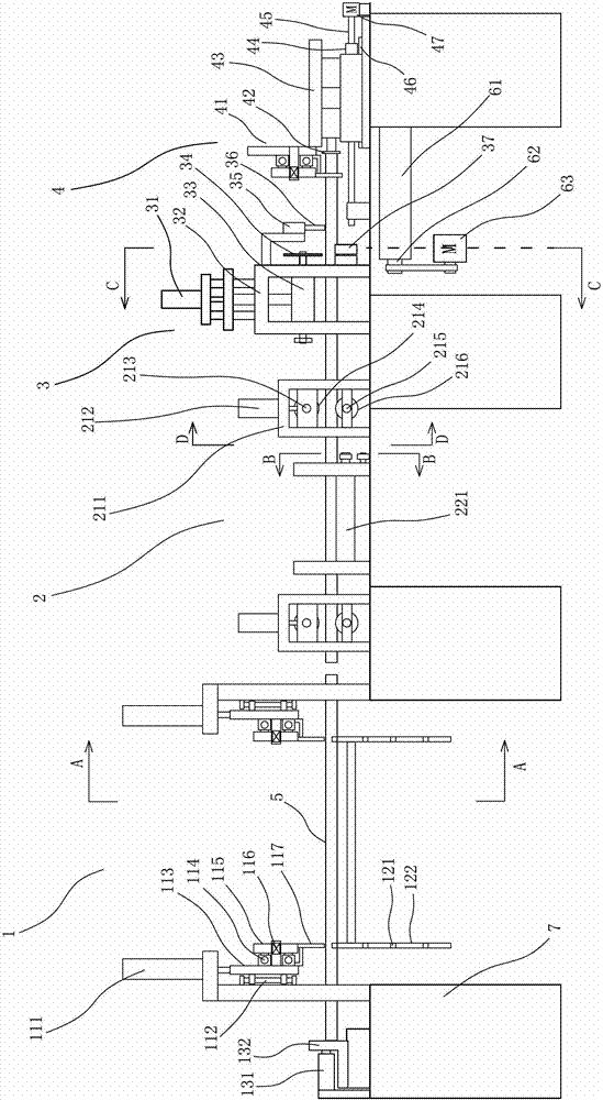
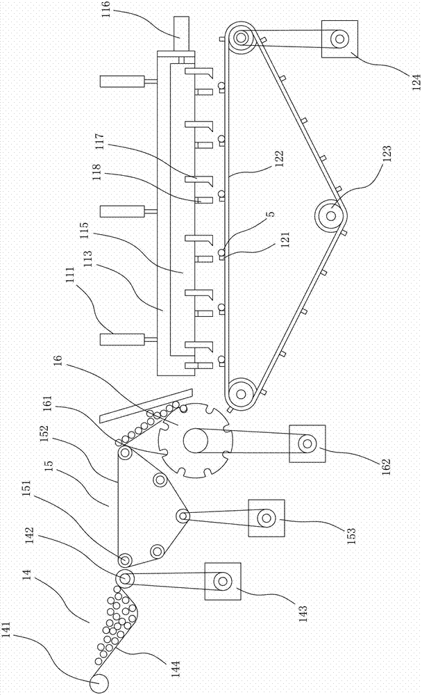
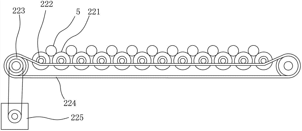
[0024] refer to Figure 1 to Figure 5 As shown, the automatic pipe cutting machine includes a frame 7, a feeding device 1, a feeding device 2, a cutting device 3, a measuring device 4 and a control device (not shown in the figure) which are arranged horizontally and horizontally on the frame 7 in turn. ), wherein the control device is respectively connected with each device for controlling the coordinated work of each device.

[0025] The cutting device 3 includes a tool holder 32 arranged on the frame 7, a plurality of first motors 33 arranged horizontally in the longitudinal direction and arranged on the tool holder 32 to move up and down, and a first motor 33 connected to drive each first motor 33 to move up and down synchronously. A cylinder 31, a circular saw blade 34 arranged on the output shaft of each first motor 33, a second motor (not shown in the figure) drivingly connected to the input shaft of each first motor 33 through a first transmission mechanism (not shown i...


PUM


Abstract

The invention provides a full-automatic pipe cutting machine comprising a frame, and a charging device, a feeding device, a cutting device, a measuring device and a control device which are sequentially arranged on the frame horizontally; the cutting device comprises a cutter holder which is arranged on the frame, a plurality of first motors which are lined horizontally along a longitudinal direction and can be arranged on the cutter holder by moving up and down, a first cylinder which is connected with and drives each first motor to move up and down synchronously, a circular saw blade which is arranged on the output shaft of each first motor, a second motor which is in transmission connection with the input shaft of each first motor through a first transmission mechanism, and a bearing piece which is arranged on the tool rest below each circular saw blade and is used for bearing a pipe at a cut part; and the measuring device comprises a guide rail which is horizontally arranged on the frame, a slide frame which is movably arranged on the guide rail, a driving mechanism which is connected with and drives the slide frame to move along the guide rail, a pipe baffle which is arranged on the slide frame and a first pipe clamping mechanism which is horizontally arranged on the slide frame along the longitudinal direction. According to the full-automatic pipe cutting machine, more than one pipe can be cut at one time, and the machine has the advantages of high cutting efficiency, good cutting quality and the like.

Description

technical field [0001] The invention relates to a pipe cutting machine. Background technique [0002] In actual production projects, it is often necessary to cut a long pipe into several sections according to actual needs. The cutting of the pipe is done on a cutting machine. The existing cutting machine usually has only one cutting circular saw blade. Multiple sections require multiple cuts, and the cutting length needs to be measured multiple times to cut a pipe section with a specific length. In addition, the above cutting processes are all manual operations, which not only results in low cutting efficiency, large labor, and low cutting accuracy. . SUMMARY OF THE INVENTION [0003] The purpose of the present invention is to provide a fully automatic pipe cutting machine with high cutting efficiency and good cutting quality in view of the deficiencies of the prior art. [0004] The object of the present invention is achieved through the following technical solutions: ...

Claims


Application Information

Patent Timeline
Patent Type & Authority Applications(China)
IPC IPC(8): B23D45/12B23D45/10B23D47/04B23D47/00
Inventor 杨建明
Owner 冠达星股份有限公司
Learn More