Electronic vacuum pump control device, vacuum boosting system and vacuum boosting method

A technology of electronic vacuum pump and control device, which is applied in the direction of brake transmission, liquid tightness measurement using liquid/vacuum degree, brake, etc. It can solve the problem of limited braking force, inability to provide vacuum source, failure to meet brake pressure requirements, etc. problem, to achieve the effect of effective control and overtime fault detection

Active Publication Date: 2015-05-20
BEIQI FOTON MOTOR CO LTD
View PDF5 Cites 1 Cited by
  • Summary
  • Abstract
  • Description
  • Claims
  • Application Information

AI Technical Summary

Problems solved by technology

[0002] The passenger car braking technology in the prior art all adopts the hydraulic braking method. The driver applies the braking force on the brake pedal and pushes the piston in the master cylinder through the push rod to perform hydraulic activities. Due to the braking force applied by the human foot It is relatively limited and cannot meet the braking pressure requirements of the four sub-cylinders under the braking of the whole vehicle, so a vacuum booster is needed to increase the boost to the pedals. For pure electric vehicles, there is no engine, no vacuum source can be provided, and the braking system can no longer be obtained. Normal traditional vacuum sources, therefore, the emergence of electronic vacuum pumps is a quick solution to the current situation
[0003] It can be seen from the above that the control of the electronic vacuum pump is particularly important. If the control is not good, the braking effect will be poor, and it may even lead to accidents.
However, there is no control system specifically for electronic vacuum pumps in the market now, only the two states of opening and closing, and it is unable to detect the electronic vacuum pump's work overtime fault

Method used


Image

  • Electronic vacuum pump control device, vacuum boosting system and vacuum boosting method
  • Electronic vacuum pump control device, vacuum boosting system and vacuum boosting method
  • Electronic vacuum pump control device, vacuum boosting system and vacuum boosting method

Examples


Embodiment 1

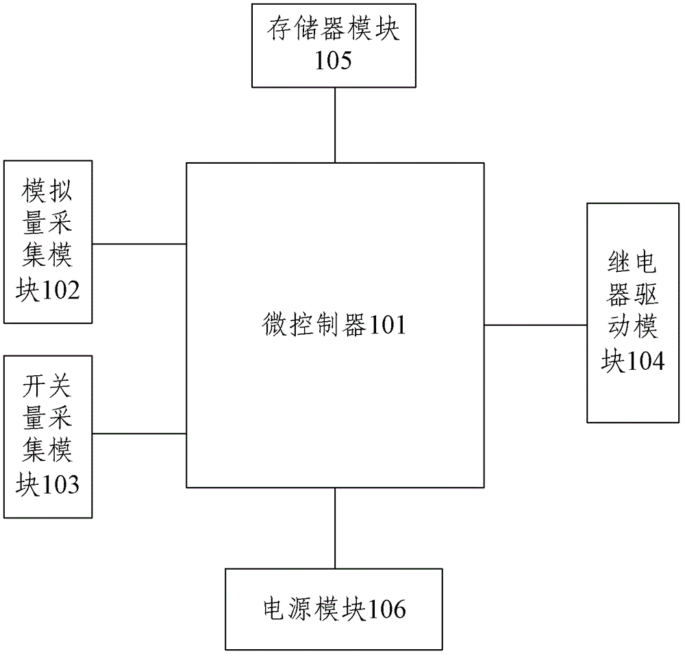
[0053] Such as figure 1 As shown, the electronic vacuum pump control device of the present invention includes: a microcontroller 101 , an analog quantity acquisition module 102 , a switch quantity acquisition module 103 , a relay drive module 104 , a memory module 105 and a power supply module 106 .

[0054] The analog quantity acquisition module 102 is connected with the microcontroller 101, filters and adjusts the analog quantity input by the pressure sensor, and sends the filtered and conditioned analog quantity to the microcontroller 101, wherein the analog quantity includes: voltage analog quantity, current Analog quantity or resistance analog quantity, the pressure sensor collects the pressure in the vacuum tank, that is, the vacuum degree, and converts the vacuum degree into voltage analog quantity, current analog quantity or resistance analog quantity, and filters and adjusts the above analog quantity, micro The A / D conversion module in the controller 101 quantizes the...

Embodiment 2

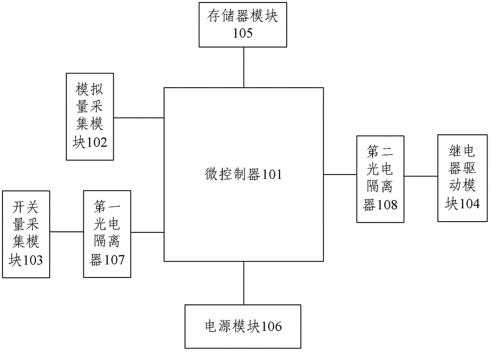
[0062] Such as figure 2 As shown, on the basis of Embodiment 1, a first photoelectric isolator 107 is added to the device, and the switching value acquisition module 103 is connected to the microcontroller 101 through the first photoelectric isolator 107 . A second photoelectric isolator 108 is also added, and the relay driving module 104 is connected to the microcontroller 101 through the second photoelectric isolator 108 .

[0063] The control flow of this embodiment is basically the same as that of Embodiment 1, the difference being that, in order to protect the microcontroller 101 (because the voltage and current that the microcontroller can withstand is relatively small), in case the sign collected by the switching value acquisition module 103 When the voltage or current value in the on / off state is too large, the microcontroller 101 is burned out, and the first photoelectric isolator 107 plays the role of reducing the voltage or current. Similarly, the second photoelect...

Embodiment 3

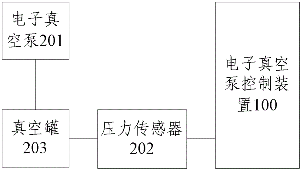
[0065] Such as image 3 As shown, the vacuum boosting system of the present invention includes: an electronic vacuum pump 201 , a pressure sensor 202 , a vacuum tank 203 and the electronic vacuum pump control device 100 of the above-mentioned embodiment 1 or 2. The electronic vacuum pump 201 and the vacuum tank 203 are connected through a vacuum tube; the pressure sensor 202 is connected to the vacuum tank 203 for real-time detection of the vacuum degree in the vacuum tank 203 . The electronic vacuum pump control device 100 is connected with an electronic vacuum pump 201 and a pressure sensor 202 , wherein the microcontroller 101 judges the airtightness of the vacuum tank 203 according to the change of the vacuum degree detected by the pressure sensor 202 .

[0066] The microcontroller 101 specifically includes: a vacuum degree acquisition module and an airtightness detection module, the vacuum degree acquisition module is connected to the analog quantity acquisition module 10...


PUM


Abstract

The invention discloses an electronic vacuum pump control device and relates to vacuum boosting system tightness detection. The electronic vacuum pump control device comprises a microcontroller, an analog quantity acquisition module, a switching quantity acquisition module, a relay driving module, a memory module and a power supply module, wherein the analog quantity acquisition module, the switching quantity acquisition module, the relay driving module, the memory module and the power supply module are connected with the microcontroller. The invention additionally discloses a vacuum boosting system, which comprises the electronic vacuum pump control device, a vacuum tank, an electronic vacuum pump and a pressure sensor. The invention additionally discloses a vacuum boosting method. Due to the electronic vacuum pump control device, the effective control on the electronic vacuum pump is realized; and due to the vacuum boosting system, the tightness detection on the vacuum tank is realized and the overtime fault detection of the electronic vacuum pump during operation is realized.

Description

technical field [0001] The invention relates to the technical field of airtightness detection of a vacuum boosting system, in particular to a vacuum pump control device, a vacuum boosting system and a vacuum boosting method. Background technique [0002] The passenger car braking technology in the prior art all adopts the hydraulic braking method. The driver applies the braking force on the brake pedal and pushes the piston in the master cylinder through the push rod to perform hydraulic activities. Due to the braking force applied by the human foot It is relatively limited and cannot meet the braking pressure requirements of the four sub-cylinders under the braking of the whole vehicle, so a vacuum booster is needed to increase the boost to the pedals. For pure electric vehicles, there is no engine, no vacuum source can be provided, and the braking system can no longer be obtained. Normal traditional vacuum sources, therefore, the emergence of electronic vacuum pumps is a q...

Claims


Application Information

Patent Timeline
Patent Type & Authority Patents(China)
IPC IPC(8): B60T13/52B60T13/72G01M3/34
Inventor 郭齐杰梁瑞石心陈飞虎周平左从兵
Owner BEIQI FOTON MOTOR CO LTD
Why Eureka
Try Eureka