Nonwoven fabric felt unrolling frame

A technology of non-woven fabrics and felt frames, which is applied in the directions of winding strips, thin material processing, transportation and packaging, etc., can solve the problems of unadjustable tension, influence of textile quality, and inability to provide surface tension of non-woven fabrics, to ensure Stability and reliability, solid overall structure, and the effect of improving unwinding efficiency

Inactive Publication Date: 2012-12-12
CHANGZHOU DIBA TEXTILE MACHINERY
View PDF5 Cites 3 Cited by
  • Summary
  • Abstract
  • Description
  • Claims
  • Application Information

AI Technical Summary

Problems solved by technology

[0002] When the textile machine is weaving, the cloth surface needs to maintain tension to achieve high-quality textile. The existing tensioning device is either a simple tensioning pulley of the transmission belt, or a separate felt rack with non-adjustable tension. The simple transmission belt tension The tight wheel structure cannot meet the tension requirements of wide-format textiles. The tension cannot be adjusted by a separate felt frame, which cannot meet the long-term textile needs, because the tension of the cloth surface will change for a long time. When the changes accumulate more and more It cannot meet the textile requirements; the above-mentioned tensioning methods will eventually affect the textile quality, and they cannot provide the non-woven fabric surface tension required by the permanent textile machine

Method used


Image

  • Nonwoven fabric felt unrolling frame
  • Nonwoven fabric felt unrolling frame
  • Nonwoven fabric felt unrolling frame

Examples


specific Embodiment approach

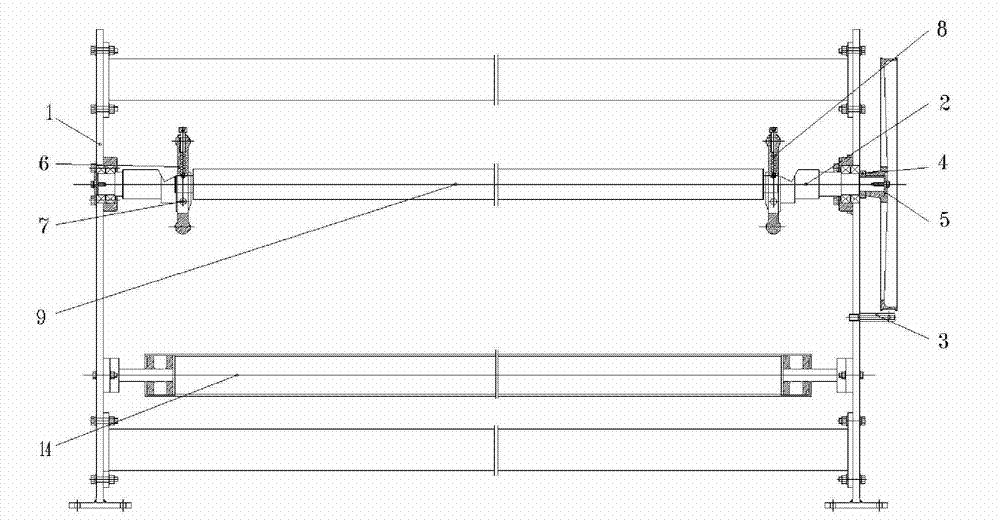
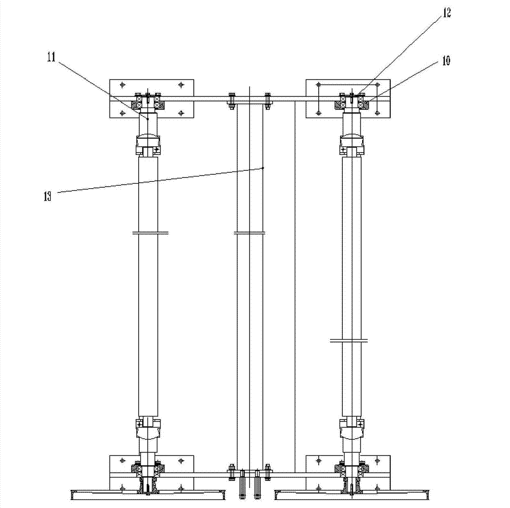
[0023] Figure 1-3 The structure of an embodiment of the present invention is shown. As shown in the figure, in the present invention, two felt rack wall panels 1 are included, the two wall panels are fixed, and the two felt rack wall panels 1 are connected and tightened. Rod 13, the two ends of tension rod 13 are fixed on the sides of the left and right wallboards by bolts; a felt guide roller 14 is also installed between the two felt rack wallboards 1, and the felt guide roller 14 is installed near the bottom of the wallboard, and the felt guide roller 14 The two ends are rotated and installed on the side walls of the two wall panels;

[0024] The two sides of the above-mentioned two felt frame wallboards 1 are also equipped with two inflatable shafts 9, the components installed on the two inflatable shafts 9 are the same, and the paper tube of the non-woven fabric roll is set on the body of the inflatable shaft 9. Above; one end of the inflatable shaft 9 is provided with a...


PUM


Abstract

The invention provides a nonwoven fabric felt unrolling frame which can keep constant tensioning force with a nonwoven fabric knitting unit during unrolling of nonwoven fabrics. The nonwoven fabric felt unrolling frame comprises two wall plates of the felt unrolling frame, and a tensioning rod, a felt guide roller and two pneumatic tensioning shaft are connected between the two wall plates. A main shaft head is arranged at one end of the pneumatic tensioning shaft while an auxiliary shaft head is arranged at the other end of the pneumatic tensioning shaft, and a safety flange is mounted on the inner side of each of the main shaft head and the auxiliary shaft head and on the pneumatic tensioning shaft. Bearing blocks are mounted on the inner wall of the two wall plates of the felt unrolling frame corresponding to the left end and the right end of the pneumatic tensioning shaft, the main and auxiliary shaft heads of the pneumatic tensioning shaft are mounted in bearings of the bearing blocks, a fixed plate is mounted outside the auxiliary shaft head, and the main shaft head penetrates through the bearing blocks to extend outside the wall plates. A retaining belt pulley spacer ring is sleeved on a portion, close to the end, of the main shaft head. A brake wheel is mounted at the end of the main shaft head through bolts, and a supporting column horizontally extends outwards on the wall plate at the mounting end of the brake wheel and is positioned below the brake wheel. A brake belt is sleeved on the brake wheel, a connecting plate is fixed to the end of the brake belt, a hook is fixed to the bottom end of the connecting plate through a hook screw, a hanging plate is hung at the bottom of the hook, and a counter weight is placed on the hanging plate.

Description

technical field [0001] The invention relates to non-woven fabric spinning equipment, which is specifically applied to the unwinding of non-woven fabrics. Background technique [0002] When the textile machine is weaving, the cloth surface needs to maintain tension to achieve high-quality textile. The existing tensioning device is either a simple tensioning pulley of the transmission belt, or a separate felt rack with non-adjustable tension. The simple transmission belt tension The tight wheel structure cannot meet the tension requirements of wide-format textiles. The tension cannot be adjusted by a separate felt frame, which cannot meet the long-term textile needs, because the tension of the cloth surface will change for a long time. When the changes accumulate more and more It cannot meet the textile requirements; the above-mentioned tensioning methods will eventually affect the textile quality, and they cannot provide the non-woven fabric surface tension required by the pe...

Claims


Application Information

Patent Timeline
Patent Type & Authority Applications(China)
IPC IPC(8): B65H16/06B65H23/16
Inventor 谈昆伦陈亚飞陈龙谈良春
Owner CHANGZHOU DIBA TEXTILE MACHINERY
Why Eureka
Try Eureka