

Oscillating spring bolt for door lock
A swing-type door lock technology, which is applied in building locks, buildings, building structures, etc., can solve the problems of unreliable positioning of the door leaf, smaller bevel angle of the tongue surface, and larger door pushing force, and achieve lengthening and reduction. Small push force, easy to push the door in and out
Active Publication Date: 2012-12-12
SHANGHAI YANGYANG DADUOLI HARDWARE PROD CO LTD +1
View PDF10 Cites 1 Cited by
- Summary
- Abstract
- Description
- Claims
- Application Information
AI Technical Summary
Problems solved by technology
When this kind of door lock with fixed tongue surface oblique angle and fixed tongue length is used on the above-mentioned false cover door, some problems sometimes occur: when the tongue surface of the dead bolt 1 or the contact surface of the lock box is not smooth, the door will It will feel very heavy; when the door gap between the door leaf and the door frame is large, the depth of the deadbolt 1 extending into the lock box is not enough, resulting in unreliable positioning of the door leaf; etc.
Although this patent application solves the problem of unreliable positioning of the door leaf, it also produces the phenomenon that the bevel angle of the tongue surface becomes smaller, which leads to a larger push force and even the self-locking of the door leaf
Method used
View moreImage
Smart ImageViewing Examples

Examples
Embodiment 1
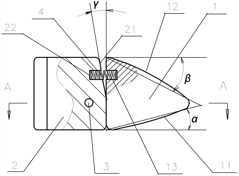
[0029] see Figure 6 , the front bevel angle α of the swinging bolt for the door lock shown in the figure is 10°, the rear bevel angle β is 30°, and the tongue seat bevel angle γ is 8°.
Embodiment 2
[0031] see Figure 7 , the front bevel angle α of the swinging bolt for the door lock shown in the figure is 18°, the rear bevel angle β is 36°, and the tongue seat bevel angle γ is 10°.
Embodiment 3
[0033] see Figure 8 , The front bevel angle α of the swinging bolt for the door lock shown in the figure is 35°, the rear bevel angle β is 45°, and the tongue seat bevel angle γ is 18°.
Login to View More PUM
 Abstract
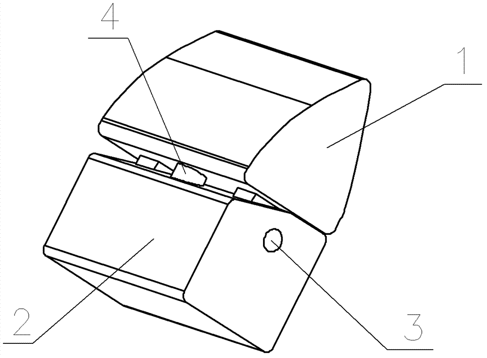
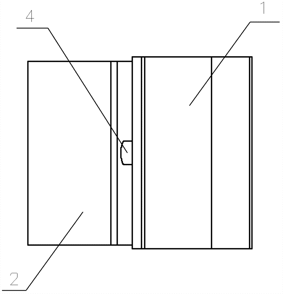
An oscillating spring bolt for a door lock is arranged on a lock body and comprises a bolt body, a bolt base, a pin shaft and elastic elements, wherein the bolt base is arranged on the lock body, and the bolt body is hinged onto the bolt base through the pin shaft and can oscillate around the pin shaft. A front bolt surface and a back bolt surface are respectively arranged on two sides of the bolt body, the front bolt surface and a door leaf plane form a front oblique angle alpha, and the back bolt surface and the door leaf plane form a back oblique angle beta. A second blind hole is arranged at the position on one side of the bolt base deviating from the pin shaft, a bolt base inclined surface is arranged on the bolt base on the periphery of the second blind hole, and the bolt base inclined surface and the vertical surface of the door leaf plane form a bolt base oblique angle gamma. A first blind hole is arranged on the bolt body at the position corresponding to the second blind hole, and the elastic elements are respectively arranged in the first blind hole and the second blind hole and push and press the bolt base and the bolt body toward two sides. The oscillating spring bolt reduces door push force, avoids door leaf self locking, ensures door leaf positioning reliability, and can be applied to various door locks, especially special unlatched doors.
Description
technical field [0001] The invention relates to a door lock of a building, in particular to a swing-type deadbolt for a door lock, which belongs to the technical field of mechanical manufacturing. Background technique [0002] Common door locks used on the doors of buildings generally include two parts: a lock body embedded in the door and a strike box fixed on the door frame. Usually the door lock locks the door by inserting and locking the deadbolt of the lock body in the catchbox, and the deadbolt is withdrawn from the catchbox by turning the handle to open the door. However, this method of opening and closing the door by manipulating the handle to control the expansion and contraction of the deadbolt seems very inconvenient in some cases, such as when there is an object in the hand and needs to pass through the door but there is no other person to assist in opening the door. ; Another example is when a waiter in a restaurant pushes the door from the kitchen to enter the...
Claims
Login to View More Application Information
Patent Timeline
 Patent Type & AuthorityApplications(China)
IPC IPC(8): E05B15/10
Inventor太田益大阪田力
OwnerSHANGHAI YANGYANG DADUOLI HARDWARE PROD CO LTD