
Suspension type tunneling frontal dust removal device

A dust removal device and a suspended technology, which is applied in the field of head-on dust removal devices for suspended excavation, can solve the problems of time-consuming and labor-intensive use, occupation of the effective space of the tail beam track of the belt conveyor, safety accidents, etc.

Inactive Publication Date: 2012-12-12
淮北市众泰机电工程有限公司
View PDF7 Cites 5 Cited by
  • Summary
  • Abstract
  • Description
  • Claims
  • Application Information

AI Technical Summary

Problems solved by technology

[0002] In order to reduce the density of dust generated during the excavation process of fully mechanized excavators, special dust removal devices are used underground to collect dust in the working environment to achieve the purpose of dust reduction. It is composed of the air cylinder between the dust collector and the water supply pipeline of the dust collector, the stop valve, and the filter pressure reducing valve. The use method is to install the dust removal device on a mobile bracket, and the small wheels at the bottom of the bracket are on the tail beam frame of the belt conveyor. This method has the following disadvantages: 1. Occupies the effective space of the tail beam track of the belt conveyor; 2. When the excavation head is extended, the suction air duct needs to be anchored again, and the steel wire is used to hang the air It is time-consuming and labor-intensive, and the labor intensity of workers is high; 3. Install the dust removal device on the belt conveyor, which may easily cause safety accidents

Method used


Image

  • Suspension type tunneling frontal dust removal device

Examples


Embodiment Construction

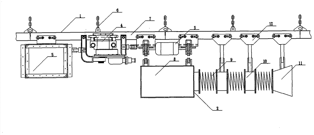
[0010] Such as figure 1 The shown suspension-type excavation head-on dust removal device includes a suspension device 1 and a dust removal device 2 connected to the suspension device, a lifting device 3, a traction device 4, and a power device 5. The dust removal device 2 is connected to the lifting device 3. The traction device 4 is connected to the lifting device 3, the power unit 5 is connected to the traction device 4, the suspension device 1 includes a hanging ring 6, a walking track beam 7, and the walking track beam 7 is connected to the hanging ring 6, and the hanging ring 6. Connect with the anchor rod or supporting I-beam or U-shaped steel elevator on the roof of the roadway.

[0011] Further, the dust removal device 2 includes a dust collector 8 , a connecting hose 9 , a connecting flange 10 , a dust suction horn 11 , and a loading vehicle 12 , wherein the dust collector 8 is connected to the dust collector through the connecting hose 9 and the connecting flange 10 ...


PUM


Abstract

The invention discloses a suspension type tunneling frontal dust removal device, which comprises a hanging device and a dust removal device, a lifting device, a traction device and a power device which are connected onto the hanging device. The dust removal device is connected with the lifting device. The traction device is connected with the lifting device, the power device is connected with the traction device, the hanging device comprises a hanging ring and a walking rail beam, the walking rail beam is connected with the hanging ring, and the hanging ring is connected with an anchor rod or a supporting double T-steel or a U-shaped steel crane which are on a top plate of a tunnel in a clamping manner. By the adoption of the dust removal device, the dust removal effect is ideal, a dust removal position is adjustable, and the operation is simple and practical; along with extension and follow-up of the tunneling frontal, the dust removal device is time-saving, labor-saving, and convenient in use, and the labor productivity can be improved; and the installation position is not affected by the height of a bottom plate of the tunnel, the dust removal device can stride over deposits and equipment on the bottom plate of the tunnel, so that a tunnel section plane is effectively utilized, the implementation of other working procedures are not interfered, and a whole course control on safe production of a fully-excavated frontal is realized.

Description

technical field [0001] The invention relates to a dust removal device, in particular to a hanging type head-on dust removal device for excavation. Background technique [0002] In order to reduce the density of dust generated during the excavation process of fully mechanized excavators, special dust removal devices are used underground to collect dust in the working environment to achieve the purpose of dust reduction. It is composed of the air duct between the dust collector and the water supply pipeline of the dust collector, the stop valve, and the filter pressure reducing valve. The use method is to install the dust removal device on a mobile bracket, and the small wheels at the bottom of the bracket are placed on the tail beam frame of the belt conveyor. This method has the following disadvantages: 1. Occupies the effective space of the tail beam track of the belt conveyor; 2. When the excavation head is extended, the suction air duct needs to be anchored again, and the...

Claims


Application Information

Patent Timeline
Patent Type & Authority Applications(China)
IPC IPC(8): E21C35/22
Inventor 梁爱霞
Owner 淮北市众泰机电工程有限公司
Learn More