
Vibration reduction lamp

A technology for lamps and vibration damping pads, which is applied in the direction of damage prevention measures for lighting devices, lighting and heating equipment, and components of lighting devices, etc. The effect of the probability of burnout

Inactive Publication Date: 2014-05-07
OCEANS KING LIGHTING SCI&TECH CO LTD +1
View PDF4 Cites 0 Cited by
  • Summary
  • Abstract
  • Description
  • Claims
  • Application Information

AI Technical Summary

Problems solved by technology

[0004] The technical problem to be solved by the present invention is to provide a lamp with simple design, low cost and good vibration damping effect in view of the defect that the light source and the lamp holder are often caused by poor contact between the light source and the lamp holder in the place of large vibration in the prior art, and the lamp is burned out. vibration damping lamps

Method used


Image

  • Vibration reduction lamp
  • Vibration reduction lamp
  • Vibration reduction lamp

Examples


Embodiment Construction

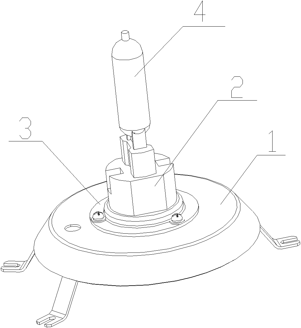
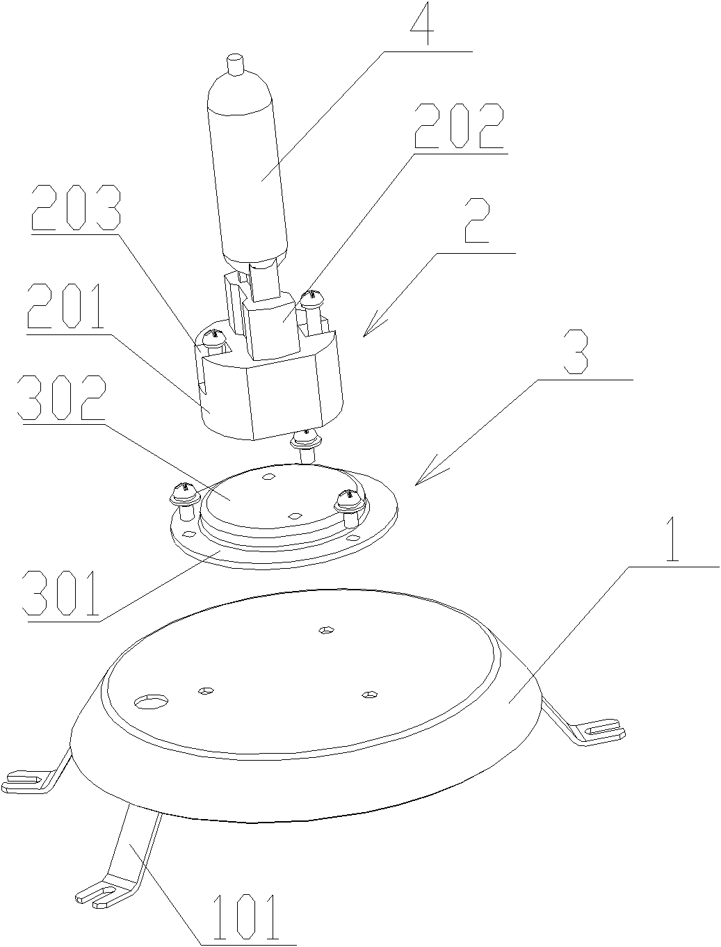
[0023] Such as figure 1 As shown, in a preferred embodiment of the present invention, the vibration-damping lamp includes a lamp body and a vibration-damping light source assembly disposed in the lamp body. figure 1 A structural schematic diagram of the damping light source assembly is given, which includes a reflector 1 , a lamp holder 2 , a flexible damping device 3 arranged between the reflector 1 and the lamp holder 2 , and a light source 4 electrically connected to the lamp holder 2 .

[0024] The upper surface of the damping device 3 is fixed in contact with the lamp holder 2, and the lower surface of the damping device 3 is fixed in contact with the reflector 1. Since the damper 3 is flexible, the distance between the light source 4 and the reflector 1 is fixed. There is no rigid connection but only flexible connection, so it can reduce the damage to the light source 4 when the lamp vibrates at high frequency, and reduce the probability of lamp burnout caused by poor co...


PUM


Abstract

The invention relates to a vibration reduction lamp which comprises a lamp body and a vibration reduction light source assembly arranged in the lamp body. The vibration reduction light source assembly comprises a light reflection plate, a lamp socket, a flexible vibration reduction device arranged between the light reflection plate and the lamp socket and a light source electrically connected with the lamp socket. By means of the vibration reduction lamp, rigid coupling between the light source and the light reflection plate is removed, damage of the lamp on the light source during high-frequency vibration is reduced, and rate of burned-out lamps caused by poor contact between the lamp socket and the light source is reduced. The vibration reduction lamp is simple in structure and low in production cost.

Description

technical field [0001] The invention relates to a lamp, more specifically, to a vibration-reducing lamp. Background technique [0002] Current professional lighting fixtures, especially lighting fixtures with relatively high precision, are often subjected to continuous and strong vibration excitation when they are used in special occasions such as airborne or shipborne, or during transportation. Large, often appear due to poor contact between the light source of the lamp and the lamp holder due to vibration, causing the lamp to burn out, thereby affecting the normal use of the lighting lamp and bringing a lot of trouble and loss to the user. [0003] Therefore, it is necessary to use a vibration reduction device to protect the professional lighting fixtures, so as to reduce the impact and vibration of the lighting fixtures from the outside world and prolong the service life of the lighting fixtures. Contents of the invention [0004] The technical problem to be solved by ...

Claims


Application Information

Patent Timeline
Patent Type & Authority Patents(China)
IPC IPC(8): F21V15/04F21V17/10
Inventor 周明杰梁校津
Owner OCEANS KING LIGHTING SCI&TECH CO LTD
Learn More