Method for measuring cone angle of cone mirror

A measuring method and technology of cone lens, applied in the field of optical measurement, to achieve the effect of less experimental instruments, convenient operation and simple principle

Inactive Publication Date: 2012-12-12
INST OF OPTICS & ELECTRONICS - CHINESE ACAD OF SCI
View PDF3 Cites 12 Cited by
  • Summary
  • Abstract
  • Description
  • Claims
  • Application Information

AI Technical Summary

Problems solved by technology

This method also belongs to the contact measurement and is n

Method used


Image

  • Method for measuring cone angle of cone mirror
  • Method for measuring cone angle of cone mirror
  • Method for measuring cone angle of cone mirror

Examples


Embodiment 1

[0045] Embodiment 1: utilize measuring device to realize the high-precision measurement of cone angle, to a measured axicon 3 is the concrete measurement of the cone angle of measured conical mirror and the adjustment steps are described as follows:

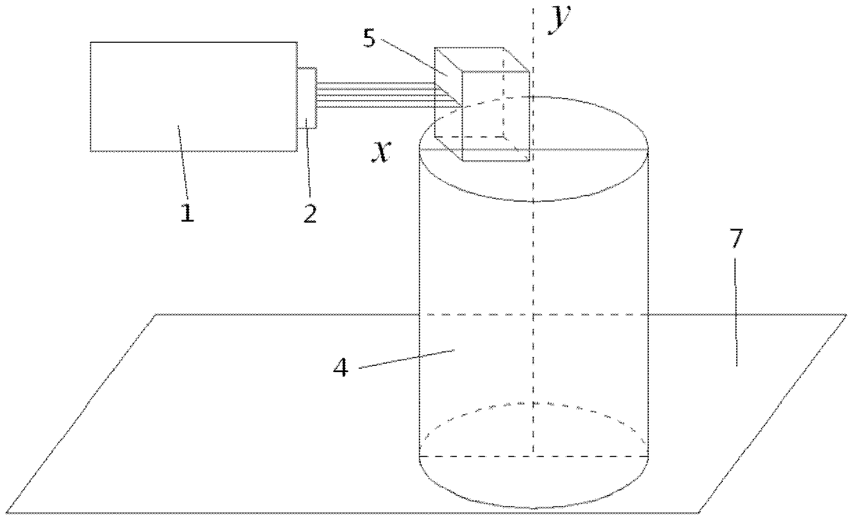
[0046] 1) Install the plane lens 2 on the interferometer 1, fine-tune the inclination and pitch of the interferometer 1, so that the parallel light emitted by the plane lens 2 is a standard parallel light; fix the cube 5 on the plane of the rotating platform 4, Rotate the rotating platform 4 so that the reflected light from one of the surfaces of the cube 5 can enter the interferometer 1, and the reflected light and the reference light in the interferometer 1 form interference fringes, such as figure 1 As shown; the tilt and pitch of the rotating platform 4 and the horizontal direction of the optical platform are fine-tuned, and the rotating platform 4 is also slightly rotated to adjust the interference fringes in the interferomet...

Embodiment 2

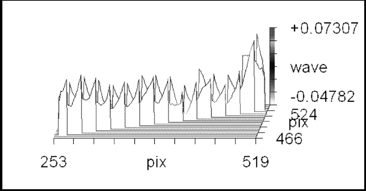
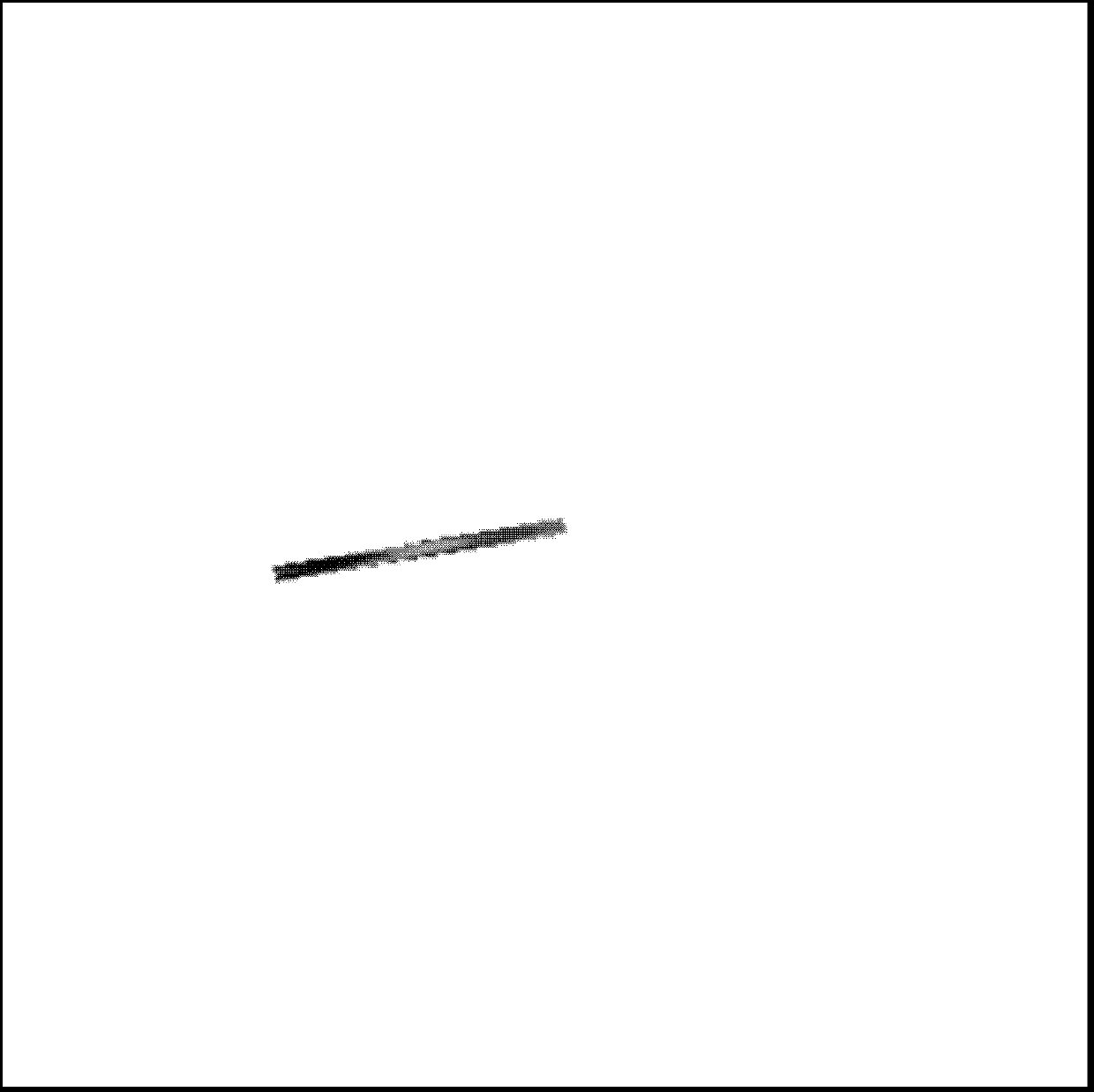
[0051] Embodiment 2: utilize measuring device to realize the high-precision measurement of cone angle, provide the embodiment that measured axicon 3 is the measured triangular axicon, specific description: step 1-4 is identical with embodiment 1, and difference is: with Conical mirrors are different. The area used for self-collimation reflection of triangular aconic mirrors is a plane. Therefore, in steps 2 and 3, it is necessary to adjust the conical surface of the triangular aconic mirror to be perpendicular to the optical axis of parallel light, and use the self-collimating reflection of the conical surface The light forms zero interference fringes with the reference beam inside the interferometer 1. Since the area of ​​the cone surface is relatively large, the shape of the formed interference fringes is easier to distinguish. The zero interference fringes formed will be in Figure 3C The interference fringe distribution map in shows zero fringes, in Figure 3A The root m...


PUM


Abstract

The invention relates to a method for measuring the cone angle of a cone mirror, which utilizes a device comprising an interferometer, a standard plane mirror, the measured cone mirror, a rotating platform, a cube and an optical platform. Firstly, the rotating platform is vertical to an optical axis; then the measured cone mirror is placed at the center of the rotating platform; one generating line or one conical surface of the cone mirror is regulated to be vertical to the optical axis; by utilizing the auto-collimation reflection of the generating line and the surrounding region thereof or the conical surface, zero-interference strips are formed by reference light inside the interferometer; the rotating platform is rotated so that the other generating line or the other conical surface at the side corresponding to the rotating platform is vertical the optical axis, and the zero-interference strips are formed in the same way; and at the time, the rotating angle of the rotating platform and the cone angle are supplementary angles, so that the accurate value of the cone angle can be calculated. The detection method provides an effective method for measuring the cone angle under the high accuracy, has a simple structure and has high application value.

Description

technical field [0001] The invention belongs to the technical field of optical measurement, and in particular relates to a method for measuring the cone angle of an axicon. Background technique [0002] With the development of modern optical processing technology, the requirements for high-precision detection of the cone angle of the axicon are constantly increasing. Accurate cone angle parameters of axicon have important engineering significance for its processing and use. The premise of high-precision measurement of the cone angle of the processed axicon is to ensure that the cone surface of the axicon will not be damaged during the measurement process. At present, there are few reports on high-precision detection methods for the cone angle of axicons. Ordinary cone angle measurement methods are generally aimed at metal cones, which are not completely applicable to glass cone mirrors. Moreover, these measurement methods are difficult to meet the requirements of high pre...

Claims


Application Information

Patent Timeline
IPC IPC(8): G01B11/26
Inventor 陈强李世杰万勇建侯溪张晶
Owner INST OF OPTICS & ELECTRONICS - CHINESE ACAD OF SCI
Why Eureka
Try Eureka