
Free float type belt weighing device

A belt weighing and floating technology, applied in the direction of measuring devices, detailed information of weighing equipment, weighing equipment for continuous material flow, etc., can solve the problem that the limiting force or internal stress cannot be released well, and cannot provide high precision Weighing measurement, interference with accurate measurement of gravity and other problems, to achieve the effect of accurate and reliable weight measurement, wide practicability, and strong anti-eccentric load ability

Active Publication Date: 2015-01-07
SAIMO ELECTRIC +1
View PDF12 Cites 0 Cited by
  • Summary
  • Abstract
  • Description
  • Claims
  • Application Information

AI Technical Summary

Problems solved by technology

[0002] At present, the weighing device of the multi-roller belt scale used for continuous weighing of belt conveyor materials has various structural forms such as single lever, double lever, and suspension scale frame. The connection between the load cell and the scale frame is mostly rigid. Connections, most of which are equipped with lateral force limiting devices, this type of connection has a certain limiting force or internal stress, which cannot be released well, which interferes with the accurate measurement of gravity, especially for a small amount of gravity or Working conditions with small changes in gravity, which will interfere with the accuracy of the final measurement results of the belt scale, and cannot provide high-precision weighing measurement

Method used


Image

  • Free float type belt weighing device
  • Free float type belt weighing device
  • Free float type belt weighing device

Examples


Embodiment 1

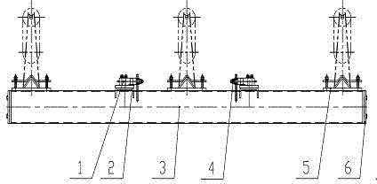
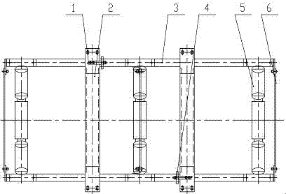
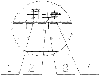
[0017] Such as figure 1 , 2 , 3 shows a free-floating belt weighing device with three idlers, the weighing device is mainly composed of a load cell 1, a support beam 2, a support beam 3, a universal joint 4, a weighing idler bracket 5, and a connecting plate 6 components, wherein the weighing idler bracket 5 is three groups, and the weighing idler bracket 5, the connecting plate 6 and the support beam 3 are connected to form a weighing bridge. The three sets of weighing idler brackets 5 are all of trough-shaped idler structure, flat idler structure or V-shaped idler structure. In the middle of a weighing idler bracket 5, there are two symmetrically installed on the belt frame beam. Supporting beam 2, two supporting beams 2 are respectively located between three sets of weighing idler brackets 5, and two supporting beams 2 are provided with two load cells 1 arranged diagonally and oppositely, that is, one is installed on each supporting beam 2 The load cell 1, the force-beari...

Embodiment 2

[0019] Such as Figure 4 , Figure 5 As shown, it is a free-floating belt weighing device with double rollers. The weighing device is mainly composed of a load cell 1, a support beam 2, a support beam 3, a universal joint 4, a weighing idler bracket 5, and a connecting plate 6 , wherein the weighing idler bracket 5 is two groups, and the weighing idler bracket 5, the connecting plate 6 and the support beam 3 are connected to form a weighing bridge. The two sets of weighing roller brackets 5 are trough roller structures, flat roller structures or V-shaped roller structures, and a support beam 2 is arranged between the two weighing roller brackets 5, and the support beam 2 is installed on the belt frame On the beam, two load cells 1 arranged oppositely are arranged symmetrically at both ends of the support beam 2, and the two load cells 1 are respectively connected to the support beam 3 through universal joints 4, and the load-bearing end structure of the load cell 1 is Cylind...


PUM


Abstract

Disclosed is a free floating type belt weighing apparatus, the apparatus mainly consisting of weighing sensors (1), bearing beams (2), bracket beams (3), universal joints (4), weighing supporting roller brackets (5) and connecting plates (6), wherein two weighing sensors (1) are mounted on the bearing beams (2), the two weighing sensors (1) are respectively connected to the bracket beams (3) via the universal joints (4), an integrated weigher frame is formed by means of the two bracket beams (3) being connected to the weigh supporting roller brackets (5) and the connecting plates (6), and the weighing sensors (1) are connected to the bracket beams (3) via the universal joints (4) such that the integrated weigher frame floats freely about the universal joints(4); therefore neither various interferences nor internal structural stresses exist. The weight of the materials on the belt is wholly and exactly transferred to the weighing sensors (1) by the weighing supporting rollers on the weigher frame such that the measuring is implemented with high precision.

Description

technical field [0001] The invention relates to a belt weighing device, in particular to a free-floating belt weighing device suitable for continuously conveying materials by a belt conveyor. Background technique [0002] At present, the weighing device of the multi-roller belt scale used for continuous weighing of belt conveyor materials has various structural forms such as single lever, double lever, and suspension scale frame. The connection between the load cell and the scale frame is mostly rigid. Connections, most of which are equipped with lateral force limiting devices, this type of connection has a certain limiting force or internal stress, which cannot be released well, which interferes with the accurate measurement of gravity, especially for a small amount of gravity or Working conditions with small changes in gravity will interfere with the accuracy of the final measurement results of the belt scale and cannot provide high-precision weighing measurement. Conte...

Claims


Application Information

Patent Timeline
Patent Type & Authority Patents(China)
IPC IPC(8): G01G11/00G01G21/02
CPCG01G11/003
Inventor 厉达
Owner SAIMO ELECTRIC
Learn More