Leakage cable clamp

A leaky cable and fixture technology, applied in cable installation, cable installation in tunnels, electrical components, etc., can solve the problems of signal interference, inconvenient work, poor firmness, etc.

Inactive Publication Date: 2012-12-12
CHINA RAILWAY SIYUAN SURVEY & DESIGN GRP
View PDF8 Cites 13 Cited by
  • Summary
  • Abstract
  • Description
  • Claims
  • Application Information

AI Technical Summary

Problems solved by technology

[0003] After the clamp itself in the prior art is installed in the tunnel, the wireless signal radiation direction of the leaky coaxial cable is only towards the axial direction of the bolt, and is perpendicular to the tunnel wall. When the leaky coaxial cable is hung outside the tunnel, the wireless The signal radiation direction faces the ground, and the natural direction of the fixture is consistent with the bolt axis. When several leaky coaxial cables are arranged horizontally, the signals of different leaky coaxial cables will interfere with each other to a certain extent. According to relevant regulations, two phases The distance between adjacent leaky coaxial cables should be greater than 0.4 meters, so some leaky coaxial cables can only be installed in positions that affect the signal coverage effect
[0004] At the same time, in the prior art, the middle part of the leaking coaxial cable clamp is provided with fixing bolts, and the bolts are mostly fixed by internal expansion bolts, and a movable metal ring with gaps is placed near the bolt head to increase the distance from the tunnel. In order to improve the signal coverage effect, but this connection method, 1, can only be fixed when the leaky coaxial cable has not been installed, so that the staff can only fix the leaky coaxial cable clamp when working at high altitude , and then clamp the leaky coaxial cable in the leaky coaxial cable clamp, but not below the leaky coaxial cable. When the cable clamp is used, it is necessary to mark the position first to ensure that the level is consistent; 2. The metal ring with gaps on the suit is easy to fall from the air during installation, and the firmness is poor after fixing, and it is easy to loosen

Method used


Image

  • Leakage cable clamp
  • Leakage cable clamp
  • Leakage cable clamp

Examples


Embodiment Construction

[0022] The specific embodiments of the present invention will be described in further detail below in conjunction with the accompanying drawings.

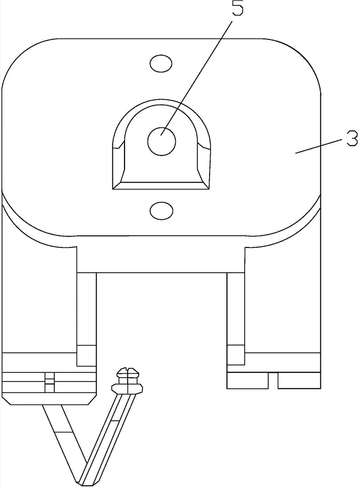
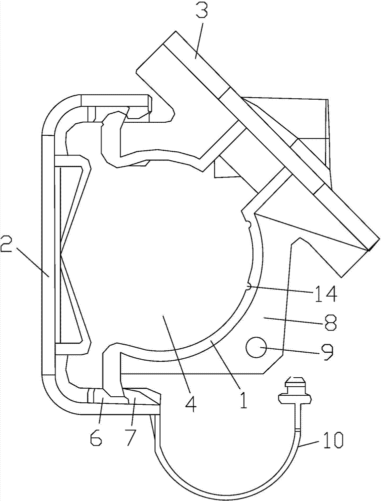
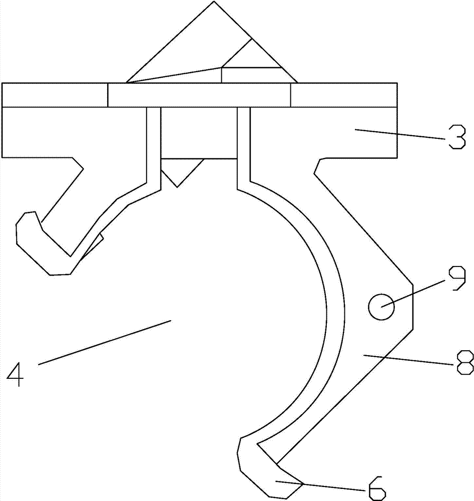
[0023] The leaky cable clamp according to the present invention includes: a support arm G-shaped seat 1 with a bottom plate and an inclined block 3 integrally constructed, the support arm G-shaped seat 1 forms a recess 4 for accommodating the leaky cable; and a cover 2 The cover body 2 and the arm-type G-shaped seat 1 can be fixedly connected by respective wedge-shaped blocks 6, 7; the cover body 2 is formed with a compressed leaky cable plate 15, which is installed in the leaky cable clamp In the state, the compressed leaky cable plate 15 is arranged opposite to the bottom surface of the arm-type G-shaped seat 1, and is clamped and locked on the arm-type G-shaped seat 1 by the cover 2 to compress the leaky cable The plate 15 is pressed against and pressed against the leaky cable in the supporting arm type G-shaped seat 1.

[0024] The...


PUM


Abstract

The invention relates to a leakage cable clamp. The leakage cable clamp comprises a corbel type G-shaped seat which is integrally structured by a bottom plate and an inclined block, and a concave part used for accumulating a leakage cable is arranged in the corbel type G-shaped seat; a cover body and the corbel type G-shaped seat can be fixedly connected through respective wedge-shaped fixture block mechanisms; a pressing leakage cable plate sheet is formed on the cover body; under the mounting state of the leakage cable clamp, the pressing leakage cable plate sheet and the bottom of the corbel type G-shaped seat are arranged oppositely, the pressing leakage cable plate sheet, at the same time of being locked through respective wedge-shaped fixture block mechanisms, abuts to and tightly presses the leakage cable in the corbel type G-shaped seat. With the adoption of the technical scheme, the orientation problem when the leakage cable is installed in a railway tunnel is ensured by the product structure to the utmost extent; in terms of the required orientation angle, if the leakage cable is arranged around 2.5 m, the horizontal direction can be formed as long as the convex conduit at the bottom of the leakage cable aligns to the sunken conduit at the lower side of the system; and corresponding radiation angles can be adjusted according to different positions of positioning grooves in terms of the other mounting heights, and thus, the orientation problem is solved.

Description

Technical field [0001] The invention relates to a cable installation clamp, in particular to a leaky cable clamp capable of offset installation of a leaky coaxial cable. Background technique [0002] In the coverage of wireless communication signals in the mountainous areas of China's railways, urban subways and highway tunnels, the wireless signal coverage in the tunnel space generally uses leaky coaxial cables plus relay equipment, and the erection height of leaky coaxial cables for railway special wireless communication is average The installation height of the leaky coaxial cable in the public network wireless communication system for signal coverage along the railway line is generally between 2.2 meters and 3.0 meters, and the installation height of the leaky coaxial cable is generally between 1.6 meters and 2.2 meters in the subway. Fixture installation. [0003] After the fixture itself in the prior art is installed in the tunnel, the wireless signal radiation direction of ...

Claims


Application Information

Patent Timeline
Patent Type & Authority Applications(China)
IPC IPC(8): H02G9/08H02G3/32
Inventor 徐璟张孟彬张健刘正自刘建宇孙峰凌力李建兵李积祥
Owner CHINA RAILWAY SIYUAN SURVEY & DESIGN GRP
Why Eureka
Try Eureka