

Rotary electric machine laminated core
A technology for a rotating electrical machine and an iron core, which is applied in the structural field of a laminated iron core, can solve the problems of reduced efficiency of the rotating electrical machine, increased torque ripple, and reduced shape accuracy, and achieves the effects of improving characteristics, reducing machining deformation, and improving productivity.
- Summary
- Abstract
- Description
- Claims
- Application Information
AI Technical Summary
Problems solved by technology
Method used
Image

Examples
Embodiment approach 1
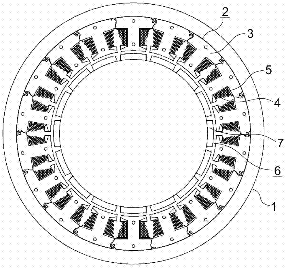
[0033] figure 1 It is a plan view showing the rotating electric machine according to Embodiment 1 of the present invention. In the figure, a cylindrical stator 2 is held in a cylindrical case 1 . The stator 2 has: a laminated core 3 ; a drive coil 4 wound around the laminated core 3 ; and an insulator 5 interposed between the laminated core 3 and the drive coil 4 .
[0034] A rotor 6 is arranged inside the stator 2 . The rotor 6 is held by the housing 1 so as to be rotatable relative to the stator 2 . The rotor 6 has a plurality of permanent magnets 7 fixed to its outer periphery and facing the stator 2 .
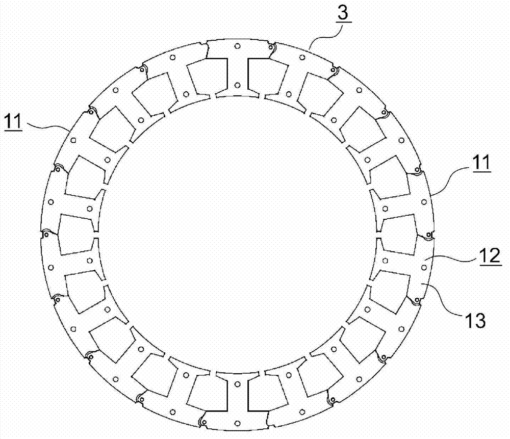
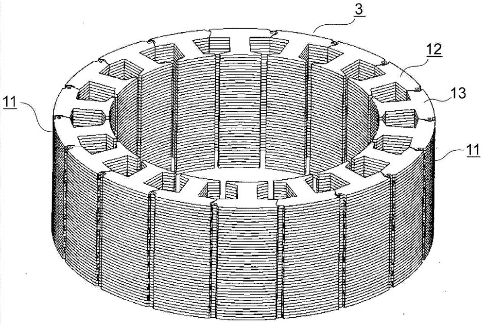
[0035] figure 2 is showing figure 1 A top view of the laminated core 3, image 3 is showing figure 1 A perspective view of the laminated core 3, Figure 4 is showing figure 1 A plan view of the laminated core 3 in the middle of assembly. Such as Figure 4 As shown, the laminated core 3 is constituted by combining a plurality (two in this example) of arc-shape...
Embodiment approach 2
[0050] Next, Figure 10 It is a plan view showing important parts of a laminated iron core of a rotating electrical machine according to Embodiment 2 of the present invention, and is the same as that of Embodiment 1. Figure 9 corresponding figure. In addition, the same code|symbol is used for the same or equivalent part as Embodiment 1, and description is abbreviate|omitted.
[0051] In the drawing, a flat portion 13h perpendicular to the magnetic pole tooth portion 13b is provided on the outer peripheral surface of the back yoke portion 13a on the radially outer side of the rotary electric machine. The flat portion 13h of each core piece 13 is provided in a state in which the divided laminated core 11 is linearly developed so that the magnetic pole teeth 13b are parallel, that is, in the state of pressing the divided laminated core 11 in the first embodiment. The flat portions 13h are located on the same straight line.
[0052] In such a laminated iron core of a rotating ...
Embodiment approach 3
[0054] Next, Figure 11 It is a plan view showing important parts of the laminated iron core of the rotating electric machine according to Embodiment 3 of the present invention, Figure 12 is to show the Figure 11 A plan view of the state where the divided laminated core 11 is unfolded in a straight line, Figure 11 and Figure 12 are the same as those of Embodiment 1 Figure 5 and Figure 9 corresponding figure. In addition, the same code|symbol is used for the same or equivalent part as Embodiment 1, 2, and description is abbreviate|omitted.
[0055] In the drawing, a holding protrusion 13i is provided at the second end of the back yoke 13a, and the holding protrusion 13i comes into contact with the protrusion 13c when the core block 12 is closed into a ring shape or an arc shape. The holding protrusion 13i is provided at the outer peripheral end of the notch 13g. In addition, when the divided laminated core 11 is unfolded in a straight line, the holding protrusion 1...
PUM
 Abstract
Description
Claims
Application Information