Ophthalmologic OCT (Optical Coherence Tomography) system and ophthalmologic OCT imaging method

A technology of ophthalmology and optical path switching, which is applied in the fields of ophthalmoscope, medical science, and eye testing equipment, etc., and can solve problems such as the inability to perform rapid and large-scale fundus scanning and imaging

Active Publication Date: 2014-07-30
SHENZHEN CERTAINN TECH CO LTD
View PDF5 Cites 1 Cited by
  • Summary
  • Abstract
  • Description
  • Claims
  • Application Information

AI Technical Summary

Problems solved by technology

Because the human eyeballs will unconsciously move slightly, and this movement can not be ignored relative to the forward and backward movement of the motor, and the OCT system in both the time domain and the frequency domain cannot achieve fast and large-scale fundus scanning imaging

Method used


Image

  • Ophthalmologic OCT (Optical Coherence Tomography) system and ophthalmologic OCT imaging method
  • Ophthalmologic OCT (Optical Coherence Tomography) system and ophthalmologic OCT imaging method
  • Ophthalmologic OCT (Optical Coherence Tomography) system and ophthalmologic OCT imaging method

Examples


Embodiment 1

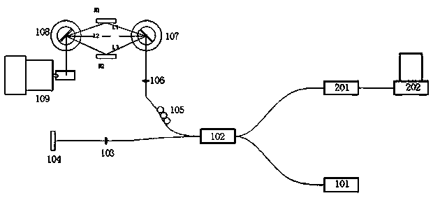
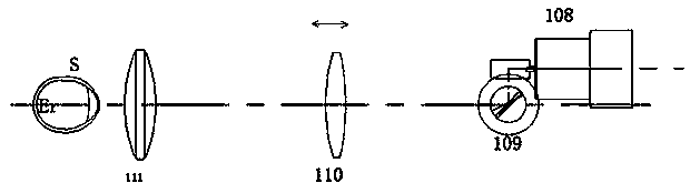
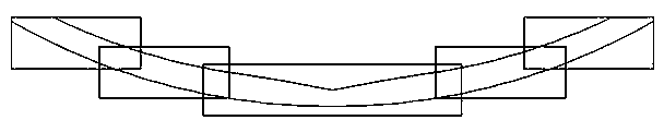
[0043] Such as figure 1 As shown, the two-dimensional vibrating mirror unit of this embodiment includes a two-dimensional vibrating mirror 108 in the X direction and a two-dimensional vibrating mirror 109 in the Y direction. The mirror unit includes two mirrors, a mirror M1 and a mirror M2. The mirror 107 includes three different corners, which correspond to three different optical paths: L1) the optical path switching vibrating mirror 107 is reflected by the mirror M1 and then exits to the center of the two-dimensional vibrating mirror 108; L2) the optical path switching vibrating mirror The outgoing light of 107 directly exits to the center of the two-dimensional vibrating mirror 108; L3) the optical path switching The outgoing light of the vibrating mirror 107 is reflected by the mirror M2 and then exits to the center of the two-dimensional vibrating mirror 108. Such as image 3 As shown, the radius of curvature of the fundus ER of the human eye is about 12.3 mm, and the i...

Embodiment 2

[0047] The difference between this embodiment and Embodiment 1 is only the reflector unit. The reflector unit in this embodiment includes three reflectors M3, M4, and M5, and the three reflectors are respectively used to form an optical path L4, L4, and L7, L6, therefore, the OCT system of this embodiment has four optical paths with different optical lengths.

Embodiment 3

[0049]The difference between this embodiment and Embodiment 1 is the mirror unit. The mirror unit of this embodiment includes four mirrors M6, M7, M8 and M9, wherein M6 and M7 are located on the optical path L8, and M8 and M9 are located on the optical path L9. superior.


PUM


Abstract

The invention discloses an ophthalmologic OCT (Optical Coherence Tomography) system and an ophthalmologic OCT imaging method. The OCT system comprises a light source, a coupler, a reference arm, a sample arm, a spectrograph and a computer processing unit, wherein the sample arm comprises a polarization controller, a sample arm focusing lens, a two-dimensional galvanometer unit, a diopter adjustment lens, an eye and object lens, a light path switching galvanometer and a reflector unit; the light path switching galvanometer comprises at least two turn angles; emergent light from a sample arm focusing lens is incident into the light path switching galvanometer and reflected by the light path switching galvanometer; the light path switching galvanometer controls the emergent angle of the emergent light through different turn angles, so that the emergent light can be incident into the two-dimensional galvanometer unit through different light paths; and the different light paths comprise a light path in which the light is directly incident into the two-dimensional galvanometer unit from the light path switching galvanometer and a light path in which the light is reflected through the reflector unit and incident into the two-dimensional galvanometer unit. According to the ophthalmologic OCT system and the ophthalmologic OCT imaging method, large-range fundus OCT scanning can be finished.

Description

technical field [0001] The present invention relates to optical coherence tomography (English: Optical Coherence Tomography, abbreviation: OCT) technology, in particular to an ophthalmic OCT system and an ophthalmic OCT imaging method. Background technique [0002] In the traditional time-domain OCT system, the reference arm vibrates to achieve a certain depth range detection, but the depth is limited. The depth position range allows the fiber optic collimator in the reference arm or the sample arm to adjust the optical path forward and backward. However, the front and back of the fiber optic collimator are often driven by motors, which cannot achieve fast switching of the detection range. In the traditional frequency-domain OCT system, the reference arm is fixed, and the optical distance is adjusted by the fiber optic collimator of the sample arm. The front and rear of the fiber collimator are also driven by motors, which cannot realize fast switching of the detection range...

Claims


Application Information

Patent Timeline
Patent Type & Authority Patents(China)
IPC IPC(8): A61B3/14A61B3/12
Inventor 蔡守东代祥松吴蕾
Owner SHENZHEN CERTAINN TECH CO LTD
Why Eureka
Try Eureka