

Method for setting vertical roll gap by centering side guide plates, measuring width and correcting
A technology of side guide plate and vertical roll, which is applied in the field of side guide plate centering, width measurement and correction of vertical roll gap setting in thick plate production. problem, achieve the effect of improving measurement and preventing abnormal rolling
Active Publication Date: 2012-12-19
BAOSHAN IRON & STEEL CO LTD
View PDF4 Cites 31 Cited by
- Summary
- Abstract
- Description
- Claims
- Application Information
AI Technical Summary
Problems solved by technology
[0006] The existing technology has the following disadvantages: In this scheme, the actual steel plate width cannot be obtained during the rolling process on site
Due to the consideration of the expected reduction in width, it is an improvement over the thick plate rolling process introduced before
Method used
View moreImage
Smart ImageViewing Examples

Examples
 PUM
| Property | Measurement | Unit |
|---|---|---|
| Thickness | aaaaa | aaaaa |
Abstract
The invention discloses a method for setting the vertical roll gap by centering side guide plates, measuring the width and correcting, comprising the following steps: receiving the size information of a steel plate by a secondary control system of a rolling mill, and calculating the pass plan, and judging whether a vertical column is used or not, wherein if the vertical column is used, the vertical-column pass process is carried out, and if the vertical column is not used, the non-vertical-column pass process is calculated. In the process of carrying out the vertical-column pass process, the width of the stretched and rolled steel plate is calculated, the steel plate is stretched and rolled according to the calculated width, and a side guide plate is centered. In the process of carrying out the non-vertical-column pass process, the width of the stretched and rolled steel plate is calculated, the steel plate is stretched and rolled according to the calculated width, and the side guide plate is centered, wherein in the process of centering the side plate, when the clamping force reaches the preset value, the opening degree of the side guide plate is measured and used as the actually-measured width, the actually-measured width is compared with the calculated width, and the vertical roll gap and the rolling force are adjusted according to the actually-measured width and the calculated width.
Description
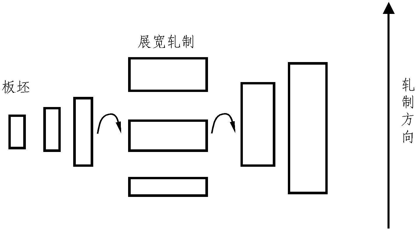
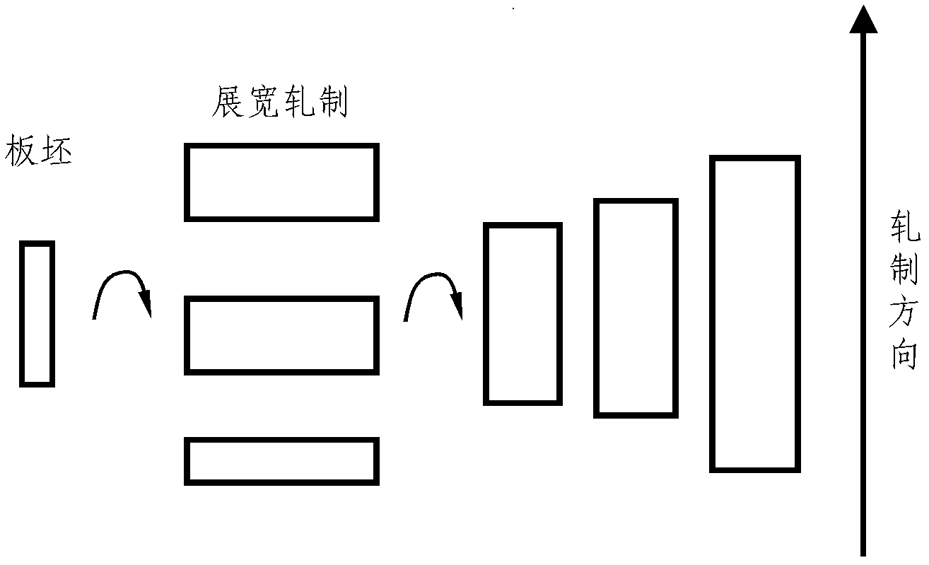
technical field [0001] The invention relates to the field of metallurgical industry, in particular to a method for centering and measuring the width of a side guide plate in the production of a thick plate to correct the roll gap setting of a vertical roll. Background technique [0002] Thick plate rolling size control is a process of rolling a slab of a certain size into a steel plate of a certain size. The width of the steel plate is generally much larger than the width of the slab, and it has widening rolling. The most common way to achieve the target steel plate size in the prior art is Figure 1a with Figure 1b Two methods are shown. [0003] The first way is as Figure 1a As shown, first roll the slab along the length direction to eliminate the deviation in the thickness direction of the slab, and carry out MAS rolling; Align the center line of the slab with the center line of the rolling mill), roll the slab along the width direction, turn the steel again after rol...
Claims
Login to View More Application Information
Patent Timeline
 IPC IPC(8): B21B37/22B21B38/04
Inventor孔伟王全胜张栋林剑
OwnerBAOSHAN IRON & STEEL CO LTD