Device and method for measuring azimuth pointing precision of radar servo base

A technology of azimuth pointing and measuring devices, which is applied in the direction of measuring devices, measuring angles, and testing of mechanical components, can solve the problems of low measurement accuracy in the external field, turntable error turntable, and low measurement accuracy, and achieve shortened measurement time and accurate measurement , The effect of simple measurement method

Pending Publication Date: 2022-01-21
HEBEI HANGUANG HEAVY IND
View PDF0 Cites 0 Cited by
  • Summary
  • Abstract
  • Description
  • Claims
  • Application Information

AI Technical Summary

Problems solved by technology

[0003] The external field measurement is mostly limited by environmental and equipment factors and the accuracy is not high, while the internal field measurement has stricter requirements on equipment and measurement methods
Typically, a method that uses the inversion of a high-precision turntable to calibrate the steering angle of the radar servo base, but this method has the disadvantages of introducing errors in the turntable and requiring high precision for the turntable; a method found on the radar servo base One reference point, after the seat body drives the reference point to rotate, use the optical equipment transfer station to measure the rotation angle difference before and after the reference point, so as to calibrate the steering angle of the radar servo seat body, but there are reference points and optical measurement transfer stations in this method. The error introduced is not easy to operate and the measurement accuracy is not high

Method used


Image

  • Device and method for measuring azimuth pointing precision of radar servo base
  • Device and method for measuring azimuth pointing precision of radar servo base

Examples


Embodiment Construction

[0022] The present invention will be described in detail below with reference to the accompanying drawings and examples.

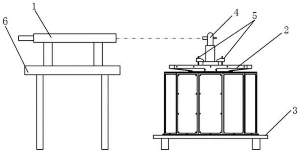
[0023] Such as figure 1 As shown, the present invention provides a measuring device for the azimuth and pointing accuracy of a radar servo base, including a collimator 1 , a high-precision adjustable platform 3 , a theodolite 4 , a fixed tooling 5 and an optical platform 6 .

[0024] Before use, the high-precision adjustable platform 3 is leveled, and the radar servo base 2 to be tested is fixedly connected to the high-precision adjustable platform 3; the collimator 1 is fixed on the optical platform 6, and the optical axis of the collimator 1 Align with the zero reticle of radar servo base 2; theodolite 4 is fixedly connected to the center of rotation of radar servo base 2, the visual axis of theodolite 4 is parallel to collimator 1, and the telescope reticle of theodolite 4 is parallel to Align the reticle line of light pipe 1, and set the azimuth angle...


PUM


Abstract

The invention discloses a device and a method for measuring the azimuth pointing precision of a radar servo base. The device comprises a collimator, a high-precision adjustable platform, a theodolite, a fixing tool and an optical platform. The collimator serves as an observation reference, software controls the radar servo base to rotate by a specific angle value, the theodolite is rigidly connected with the radar servo base, the actual rotation value of the radar servo base can be measured, and the absolute value of the difference between the azimuth feedback value of the radar servo base and the actual rotation angle value of the azimuth measured by the theodolite is calculated, and the the absolute value is the pointing precision of the radar servo base at the angle. According to the device and method, the pointing precision of the radar servo base is accurately measured in the internal field, the measuring method is simple and easy to operate, the process controllability is good, the measuring time is shortened, and the measuring precision is improved.

Description

technical field [0001] The invention relates to the technical field of debugging, in particular to a measuring device and method for the azimuth pointing accuracy of a radar servo base. Background technique [0002] With the continuous development of phased array radar technology, the precision requirements of phased array radar are getting higher and higher. As an important part of the phased array radar, the radar servo base has the functions of supporting and driving the rotation and positioning of the antenna. Its pointing accuracy directly affects the accuracy of the phased array radar antenna. Usually, the detection mechanism is used to measure the rotation angle from the initial position of the radar servo base to the target position, and compared with the rotation angle value fed back by the system, to realize the precise measurement of the pointing accuracy of the radar servo base. The measurement value of the pointing accuracy is the basis for the software to com...

Claims


Application Information

Patent Timeline
Patent Type & Authority Applications(China)
IPC IPC(8): G01S7/40G01M13/00G01C1/00
CPCG01S7/4004G01M13/00G01C1/00
Inventor 曲松耿亚光米有杰
Owner HEBEI HANGUANG HEAVY IND
Why Eureka
Try Eureka