
Calibration method for installation error of sensor module in three-dimensional space

A sensor module, three-dimensional space technology, applied in the direction of instruments, measuring devices, etc., can solve the problems of low efficiency, low accuracy, deviation of calculation results, etc., and achieve the effect of simple operation process, high-precision measurement, and reduced requirements.

Inactive Publication Date: 2018-12-28
JIANGSU UNIV
View PDF4 Cites 0 Cited by
  • Summary
  • Abstract
  • Description
  • Claims
  • Application Information

AI Technical Summary

Problems solved by technology

At present, in the process of installing and welding such products perpendicular to the horizontal plane, try to ensure that they are perpendicular to the horizontal plane. However, there will still be errors that cannot be avoided, so that the vertical axis is not in the vertical direction, and the horizontal axis is not in the horizontal direction, resulting in the final calculation. deviation of results
[0003] The traditional calibration method mainly adopts manual calibration, which has high cost, low efficiency, and low accuracy. It is obviously not suitable for the calibration of inclination sensors. There are many automatic calibration technologies, such as the inclination sensor calibration system launched by Fanhua Hengxing. Calibration based on a single-axis sensor that cannot account for tilt due to installation in 3D space
The algorithm correction method of the dual-axis inclination sensor published by the Coal Science Research Institute, using the error compensation method, needs to measure and calibrate the angle in the whole range to obtain the regression function, and then perform corresponding compensation. The process is complicated, and this algorithm mainly compensates The accuracy of the correction device itself and the error caused by drift cannot solve the error problem when installing the tilt in three-dimensional space.

Method used


Image

  • Calibration method for installation error of sensor module in three-dimensional space
  • Calibration method for installation error of sensor module in three-dimensional space
  • Calibration method for installation error of sensor module in three-dimensional space

Examples

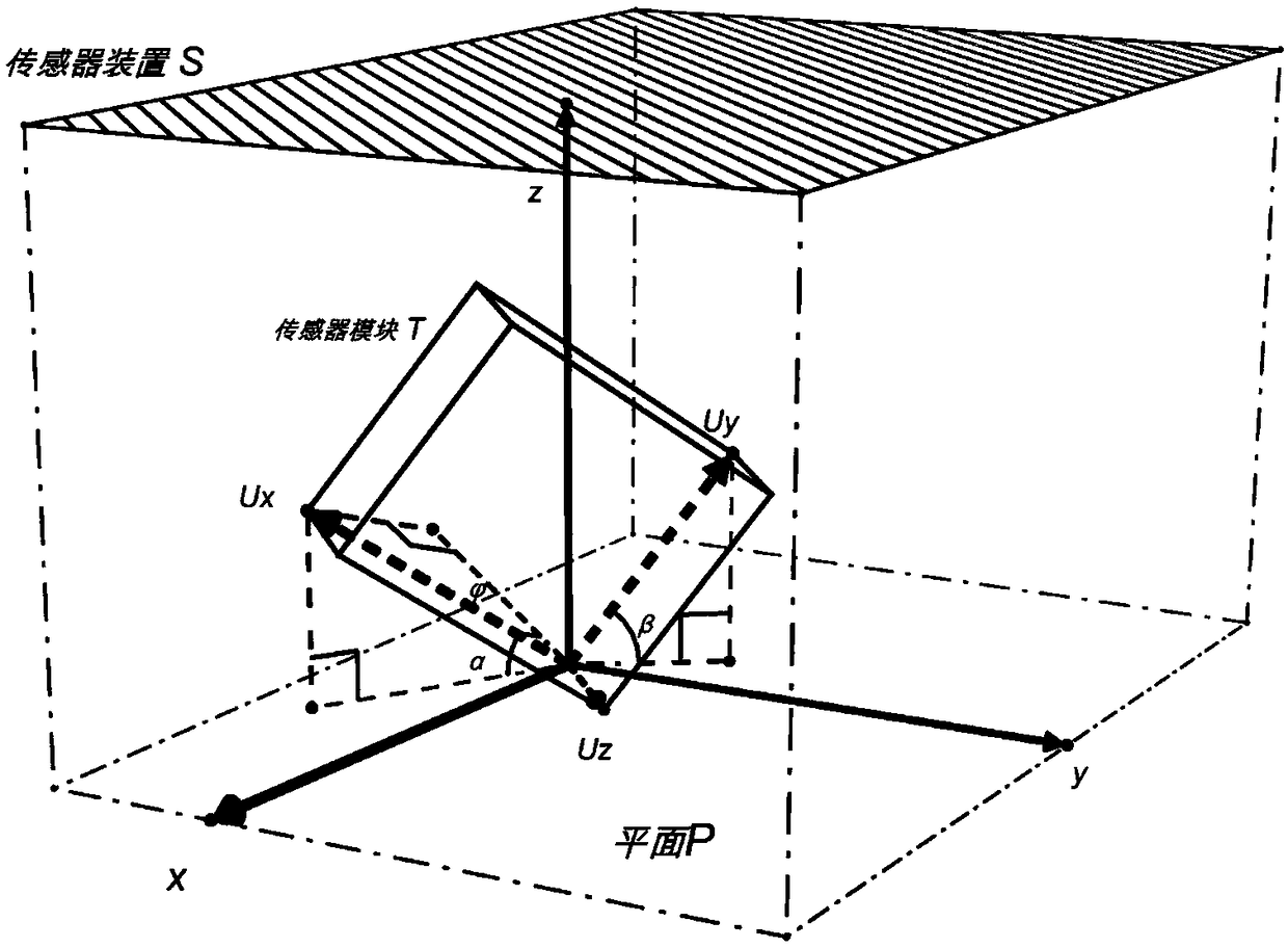
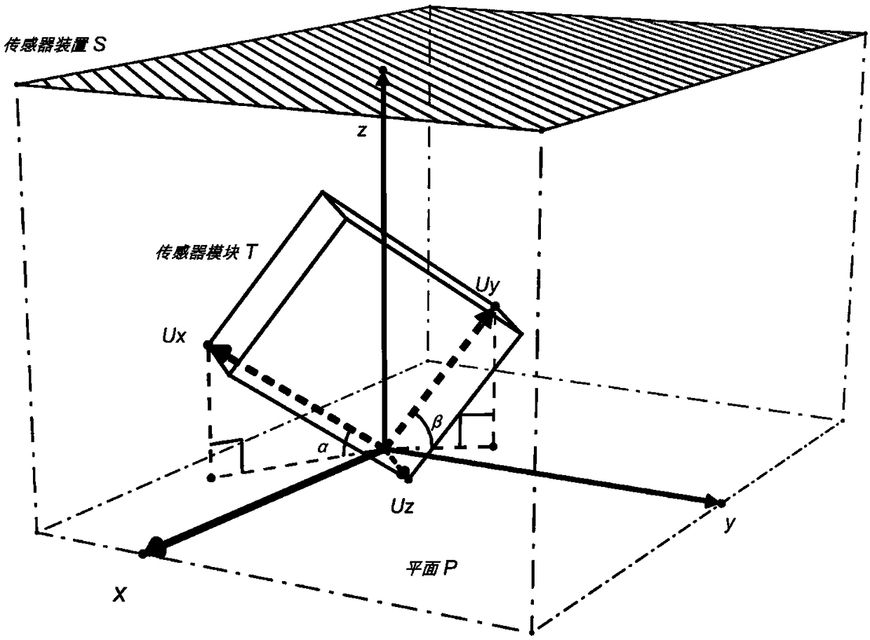
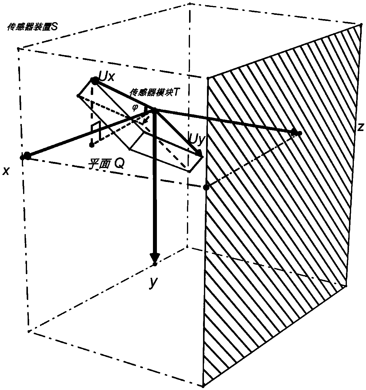

Embodiment Construction

[0025] The technical solution of the present invention will be further described below in conjunction with the accompanying drawings.

[0026] Before explaining the installation calibration algorithm, first explain the angles used and the purpose of calibration:

[0027] 1. Calibration purpose: The dotted line frame in all the drawings represents the entire sensor device S (composed of sensor module T, battery, processor, and display screen. The processor detects the value of the sensor module T, performs data processing, and then controls The display screen displays, the battery is used for power supply of the sensor module T, the processor, and the display screen, the processor is the CPU, and the model is MSP430), the xyz axis is a standard three-dimensional coordinate axis of space, and the small cube represents the inclination sensor module T (composed of two mutually perpendicular inclination sensors are integrated), and the two measurement axes of the module are mutuall...


PUM


Abstract

The invention discloses a calibration method for an installation error of a sensor module in a three-dimensional space, comprising the following three calibration steps: (1) under a graphical rectangular coordinate system in a three-dimensional space, by taking a plane P where x and y axes are located as a horizontal plane, placing a sensor device S, and measuring an included angle alpha between an axis Ux of a tilt sensor module T and the plane P and an included angle beta between an axis Uy and the plane P; (2) by taking a plane Q where x and z axes are located as a horizontal plane, placinga sensor device S, and measuring an included angle (described in the specification) between an axis Ux of a sensor module T and the plane Q; and (3) respectively obtaining vectors (described in the specification) corresponding to the axes Ux and Uy by virtue of the included angles alpha and beta and the other included angle (described in the specification), and obtaining vectors after rotation (described in the specification) by virtue of rotation matrixes corresponding to premultiplication (described in the specification), thus the axis Ux is calibrated to a forward direction of the z axis and the axis Uy is calibrated to a forward direction of the y axis. The calibration method disclosed by the invention can realize installation calibration on a relatively small deviation produced as the sensor module I is installed in the three-dimensional space, so that measurement accuracy is improved.

Description

technical field [0001] The invention relates to a calibration process after the installation of an inclination sensor module. This calibration method is also suitable for sensors installed in three dimensions in space, which require high measurement accuracy and are difficult to avoid small deviations during installation. Background technique [0002] Taking the inclination sensor as an illustration, this type of sensor is placed in space. Under different placement angles, each axis will output a voltage value at a corresponding angle. According to the obtained electrical signal and processed by a processor, the corresponding inclination value is obtained. Widely used It is used in industrial production, construction safety, national defense technology and other fields. At present, in the process of installing and welding such products perpendicular to the horizontal plane, try to ensure that they are perpendicular to the horizontal plane. However, there will still be errors...

Claims


Application Information

Patent Timeline
Patent Type & Authority Applications(China)
IPC IPC(8): G01C25/00
CPCG01C25/00
Inventor 和卫星陈琦祥曹健安
Owner JIANGSU UNIV
Learn More