Conveyor Straightening Unit

A conveyor belt and conveyed technology, applied in conveyors, conveyor objects, transportation and packaging, etc., can solve problems affecting conveying operations, conveyor belt derailment, etc., to achieve low cost, improve stability, and enhance the ability to withstand external forces Effect

Inactive Publication Date: 2014-10-08
昆山特力伯传动科技有限公司
View PDF10 Cites 0 Cited by
  • Summary
  • Abstract
  • Description
  • Claims
  • Application Information

AI Technical Summary

Problems solved by technology

Severe deviation will lead to the derailment of the conveyor belt, thus affecting the entire conveying operation

Method used


Image

  • Conveyor Straightening Unit

Examples


Embodiment Construction

[0020] Several embodiments of the present invention are discussed in detail below with reference to the accompanying drawings.

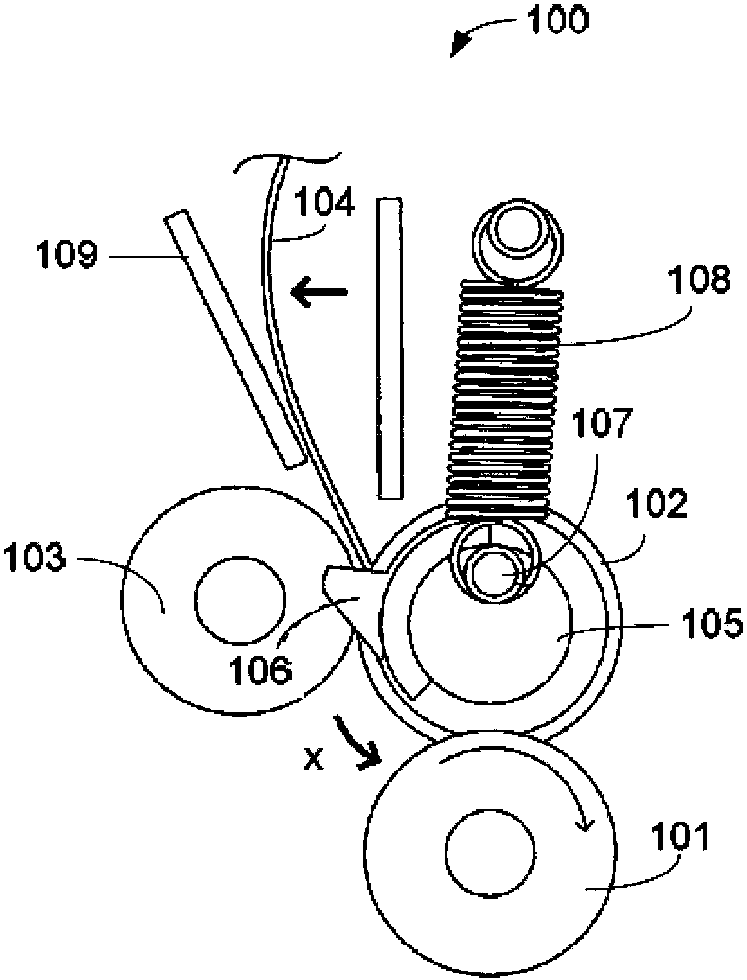
[0021] figure 1 The basic structure of the conveyor belt straightening unit of the present invention is schematically shown. As shown in the figure, the conveyor belt straightening unit 100 of the present invention mainly includes: a driving roller 101, a first driven roller 102, a second driven roller 103, a conveyor belt 104, a correction gear plate 105, a bump 106, and a stabilizing cam 107 , a stabilizing spring 108 and a baffle 109 .

[0022] refer to figure 1 , the conveyor belt 104 is conveyed between the first driven roller 102 and the second driven roller 103 and between the first driven roller 102 and the driving roller 101 .

[0023] The correction gear plate 105 is disposed on one side of the first driven roller 102 concentrically with the first driven roller 102 . In particular, the correcting gear plate 105 has a protrusion 106 , an...


PUM


Abstract

The invention provides a straightening unit of a conveying belt. The straightening unit of the conveying belt comprises a drive roller, a first driven roller, a second driven roller and a straightening shift disc, wherein the conveying belt is conveyed to pass through a part between the first driven roller and the second driven roller and a part between the first driven roller and the drive roller; and the straightening shift disc is arranged at one side of the first driven roller in the way that the straightening shift disc is concentric to the first driven roller, and is provided with a lug, and the lug covers the contact area of the first driven roller and the second driven roller. The straightening unit of the conveying belt has a simple structure and is low in cost.

Description

technical field [0001] The invention relates to the field of conveyor belts, in particular to a conveyor belt storage bin. Background technique [0002] In the middle of the 17th century, the United States began to use aerial cableways to transport bulk materials; in the middle of the 19th century, conveyor belt conveyors of various modern structures appeared one after another. In 1868, belt conveyor belt conveyors appeared in the UK; in 1887, screw conveyors appeared in the United States; in 1905, steel belt conveyors appeared in Switzerland; in 1906, inertial conveyors appeared in the UK and Germany . Since then, the conveyor belt conveyor has been continuously improved under the influence of technological progress in machinery manufacturing, electrical machinery, chemical and metallurgical industries, and has gradually developed from the completion of conveying in the workshop to the completion of material handling within the enterprise, between enterprises, and even bet...

Claims


Application Information

Patent Timeline
Patent Type & Authority Patents(China)
IPC IPC(8): B65G39/16B65G15/64
Inventor 朱井钟
Owner 昆山特力伯传动科技有限公司
Why Eureka
Try Eureka