Propelling mechanism

A push mechanism and push plate technology, applied in the direction of conveyor objects, transportation and packaging, etc., can solve the problems of high production cost, complex structure, unreliable action, etc.

Inactive Publication Date: 2012-12-19
SHANGHAI ZHILIAN PRECISION MACHINERY
View PDF8 Cites 15 Cited by
  • Summary
  • Abstract
  • Description
  • Claims
  • Application Information

AI Technical Summary

Problems solved by technology

[0002] In the prior art, the diaper production line needs to use a manipulator to push the diaper to the next working platform, but mo

Method used


Image

  • Propelling mechanism
  • Propelling mechanism
  • Propelling mechanism

Examples


Embodiment Construction

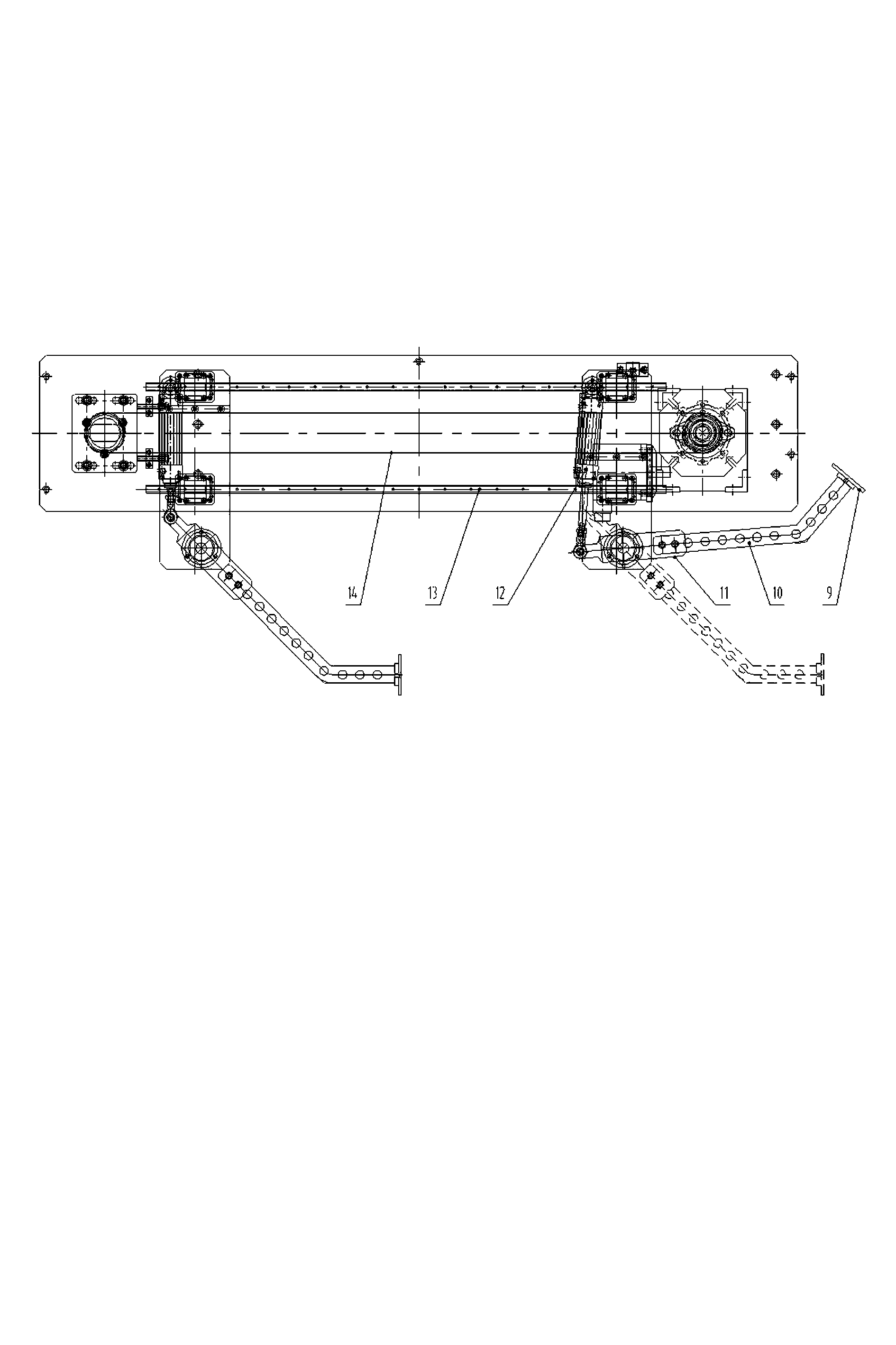
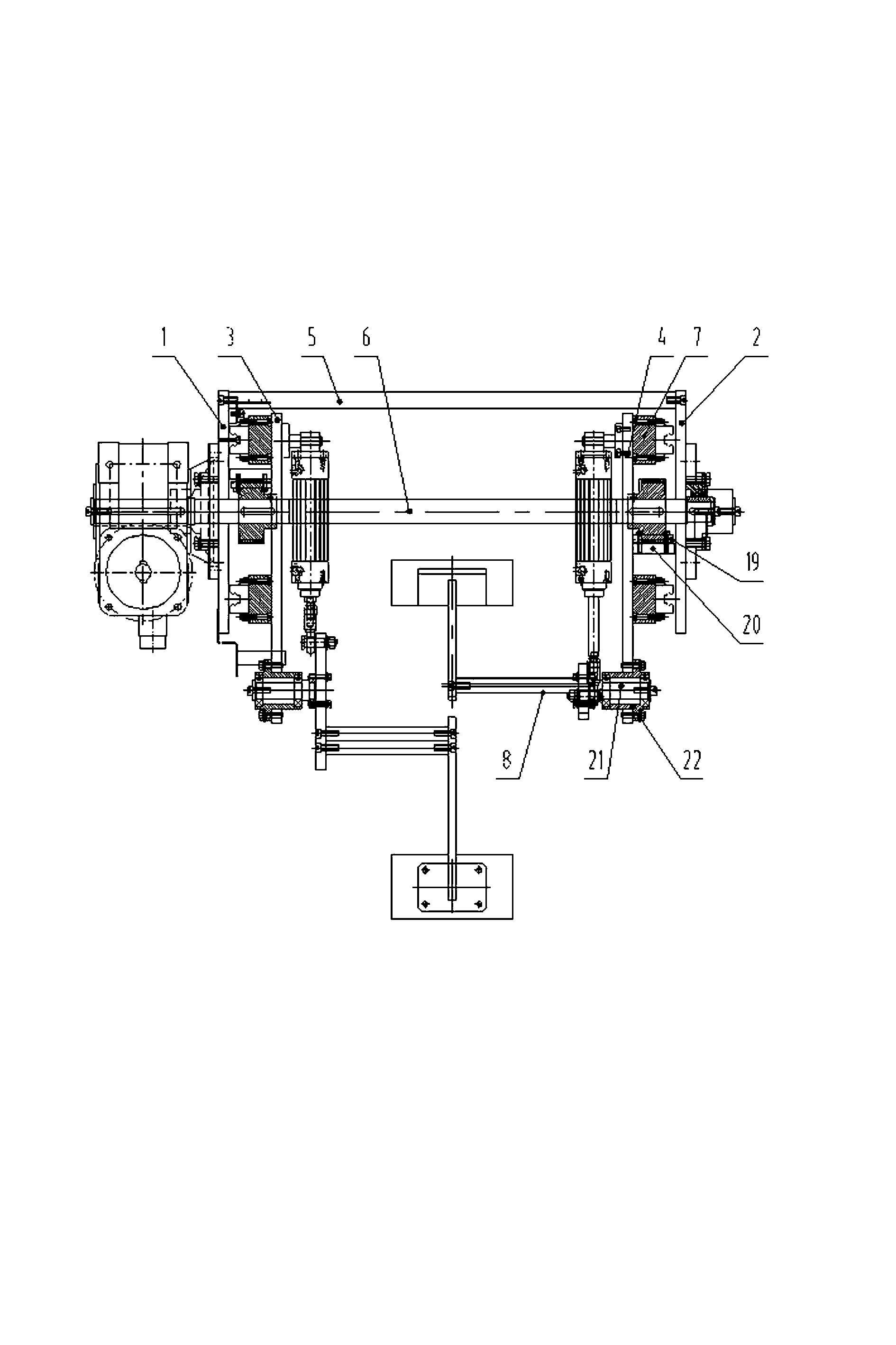
[0009] A push mechanism, including two groups of push hand mechanisms, slide plates 3, 4 are the cornerstones of the push hand mechanism, a fixed block 20 is installed on one side of the slide plates 3, 4, and the fixed block 20 is connected with a splint 19 with a toothed groove, through The splint 19 with the toothed groove can fix the left and right slide plates 3 and 4 on the left and right synchronous belts 14 respectively. 7. The other end of the connecting plate 7 is fixed on the slider of the linear guide rail 13 (the slider belongs to a part of the linear guide rail, and forms a linear motion guide rail pair together with the guide rail part of the linear guide rail). In this way, the timing belt can pull the slide plate and even all the parts installed on the slide plate move back and forth on the linear guide rail together. The other side of the slide plate is equipped with a cylinder 12 (upper position) and a bearing seat 22 (lower position), and a rotating shaft 2...


PUM


Abstract

The invention discloses a propelling mechanism which comprises guide rails arranged on a supporting plate, wherein a sliding plate is installed on a guide rail slider through a connecting piece. The propelling mechanism is characterized in that the sliding plate is equipped with a cylinder; the output end of the cylinder is connected with one end of a cylinder connecting plate, while the other end of the cylinder connecting plate is connected with a swing arm; the middle part of the cylinder connecting plate is connected with a rotating shaft arranged on the sliding plate; and a push plate is arranged at the tail end of the swing arm. The propelling mechanism disclosed by the invention has the advantages of stability in operation, safe and reliable action and low noise.

Description

technical field [0001] The invention relates to the field of diaper production, in particular to a pushing mechanism used in a production line of diapers. Background technique [0002] In the prior art, the diaper production line needs to use a manipulator to push the diaper to the next working platform, but most of the existing manipulators have disadvantages such as complex structure, high production cost, unreliable action, and loud noise. Contents of the invention [0003] The purpose of the present invention is to provide a simple and reliable pushing mechanism for the production line of diapers. [0004] In order to achieve the above object, the technical solution of the present invention is: a push mechanism, including a guide rail arranged on a support plate, the slide plate is installed on the guide rail slider through a connecting piece, and it is characterized in that a cylinder is installed on the slide plate, and the output end of the cylinder passes through ...

Claims


Application Information

Patent Timeline
IPC IPC(8): B65G47/82
Inventor 周国红夏宝印
Owner SHANGHAI ZHILIAN PRECISION MACHINERY
Why Eureka
Try Eureka