Module type moveable flood-preventing wall

A flood control wall and modular technology, applied in dikes, coastline protection, dams, etc., can solve the problems of long gate opening time, increased transportation costs, and troublesome sandbag handling, etc., and achieves the effect of convenient installation, low transportation and production costs.

Active Publication Date: 2014-09-03
上海东泽环境科技股份有限公司
View PDF5 Cites 0 Cited by
  • Summary
  • Abstract
  • Description
  • Claims
  • Application Information

AI Technical Summary

Problems solved by technology

Although stacking sandbags can have a better waterproof effect, due to the heavy weight of the sandbags, it takes more physical strength and time during the accumulation process. Besides, there are more fillers in the sandbags, plus the physical strength and time required during the accumulation process. Therefore the cost is higher
At the same time, once the sandbags are not stacked tightly enough, it will cause water leakage. In addition, after the flood season, it is also very troublesome to dispose of the used sandbags.
There are also some temporary flood control gates in the existing market, but most of them need to do a lot of civil work before installation, so the installation cycle of the gates increases, and the cost increases, causing problems such as low efficiency, and the existing flood control gates Most of the sealing strips need to be installed separately, causing the gate to open for a long time
There is also a mobile combined flood control wall. When the flood season comes, it must be transported to the original dam for combined installation, and it will be dismantled and transported away after the flood season, so the transportation cost will be increased.

Method used


Image

  • Module type moveable flood-preventing wall
  • Module type moveable flood-preventing wall
  • Module type moveable flood-preventing wall

Examples


Embodiment Construction

[0021] In order to enable those skilled in the art to better understand the technical solution of the present invention, its specific implementation will be described in detail below in conjunction with the accompanying drawings:

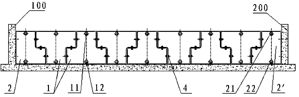
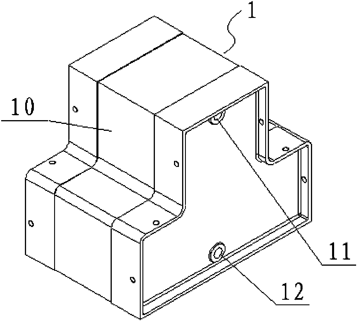
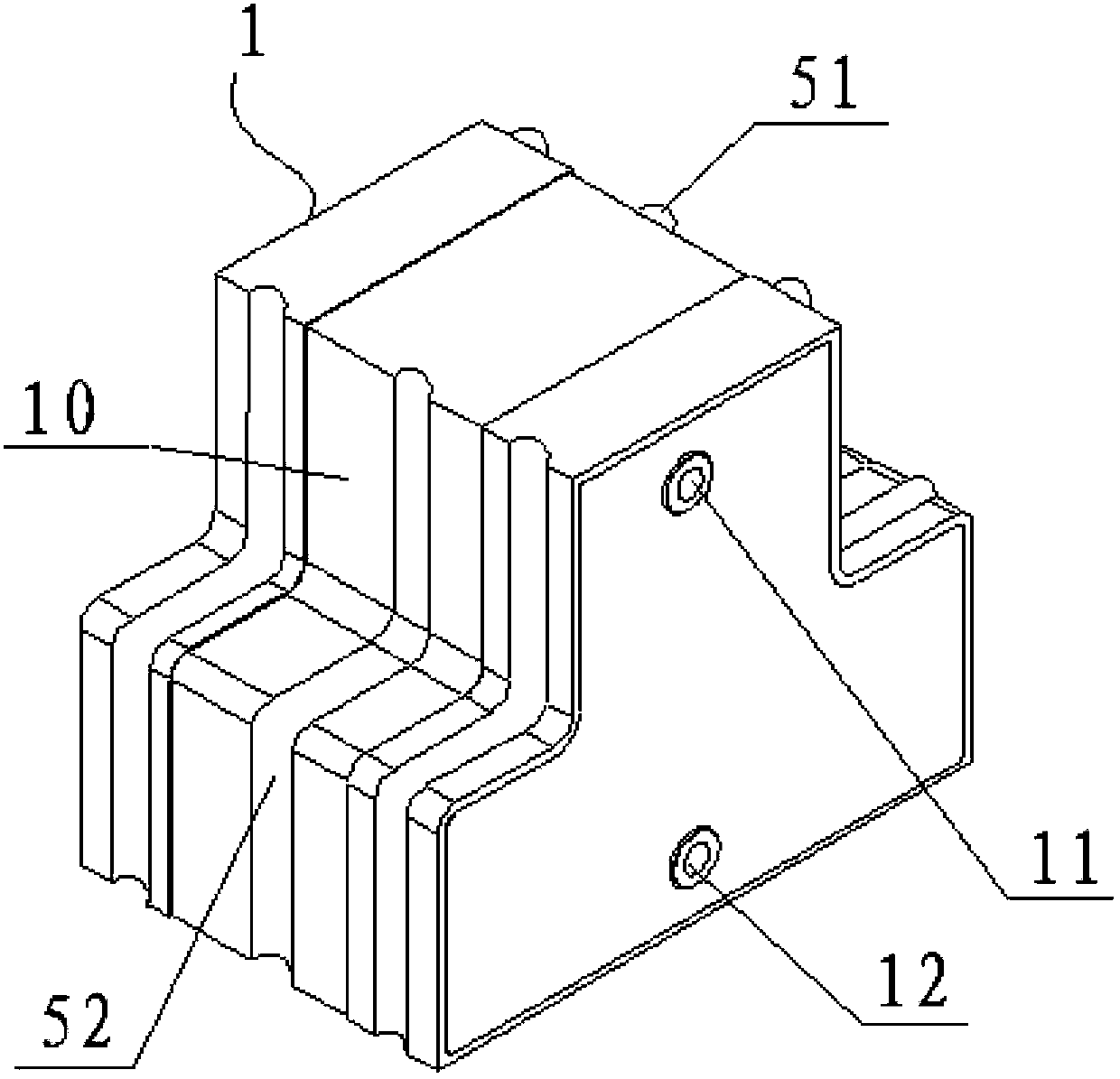
[0022] see Figure 1 to Figure 3 , a modular movable flood control wall of the present invention is installed between two building walls 100,200. The modular movable flood control wall includes several standard modules 1, a pair of end modules 2, 2', several fastening mechanisms and several connecting mechanisms, among which:

[0023] The standard module 1 is made of polyvinyl chloride plate and is a hollow block with a T-shaped cross section. Each standard module 1 is provided with a sealing strip 10 on both sides and the middle of the upper and lower end surfaces. The width of the sealing strip 10 is 1 The thickness of the sealing tape 10 is 2-5 mm; the upper and lower parts of the front face of the standard module 1 are respectively provided wit...


PUM


Abstract

The invention discloses a module type moveable flood-preventing wall which is low in manufacturing cost, convenient to transport and quickly assembled. The module type moveable flood-preventing wall comprises a plurality of standard modules and a pair of end modules and is mounted between two building walls. The standard modules are hollow blocks with T-shaped cross sections; a middle retention wall is formed by connecting the standard modules in a positive-negative splicing mode of the side surfaces of the adjacent standard modules; the end modules are hollow blocks with L-shaped cross sections; the shape and size of the curve straight side surfaces of the end modules are respectively as same as the shape and size of the side surfaces of the standard modules; flat side surfaces of the pair of end modules are connected with inner side surfaces of the building walls; the curve straight side surfaces of the pair of end modules are respectively connected with the curve straight side surfaces at two ends of the middle retention wall in the positive-negative splicing mode, so as to form the whole section of retention wall; and water injection holes with plugs are respectively formed on the upper and lower parts of the front and rear end faces of each of the standard modules and the upper and lower parts of the front and rear end faces of each of the end modules.

Description

technical field [0001] The invention relates to a flood control wall, in particular to a modular movable flood control wall. Background technique [0002] The rainy season from early June to mid-July and the typhoon season from mid-July to mid-September in my country's coastal areas are prone to flood disasters. When the flood season comes, many facilities such as underground garages, shopping malls, residential areas and other units with relatively low terrain must not only ensure a good drainage system, but also pile up some sandbags at the door to prevent ground water from flowing in and causing damage to vehicles or other property. Although stacking sandbags can have a better waterproof effect, due to the heavy weight of the sandbags, it takes more physical strength and time during the accumulation process. Besides, there are more fillers in the sandbags, plus the physical strength and time required during the accumulation process. Therefore the cost is higher. At the ...

Claims


Application Information

Patent Timeline
Patent Type & Authority Patents(China)
IPC IPC(8): E02B3/10E02B3/14
Inventor 王克陈岩朱桦
Owner 上海东泽环境科技股份有限公司
Why Eureka
Try Eureka