
Back plate component and liquid crystal display

A technology for a liquid crystal display and a backplane assembly, which is applied in the field of the backplane assembly and the liquid crystal display, can solve the problems that the thickness of the border of the liquid crystal display cannot be narrowed, and the maximum viewing area cannot be enlarged.

Active Publication Date: 2012-12-19
TCL CHINA STAR OPTOELECTRONICS TECH CO LTD
View PDF6 Cites 0 Cited by
  • Summary
  • Abstract
  • Description
  • Claims
  • Application Information

AI Technical Summary

Problems solved by technology

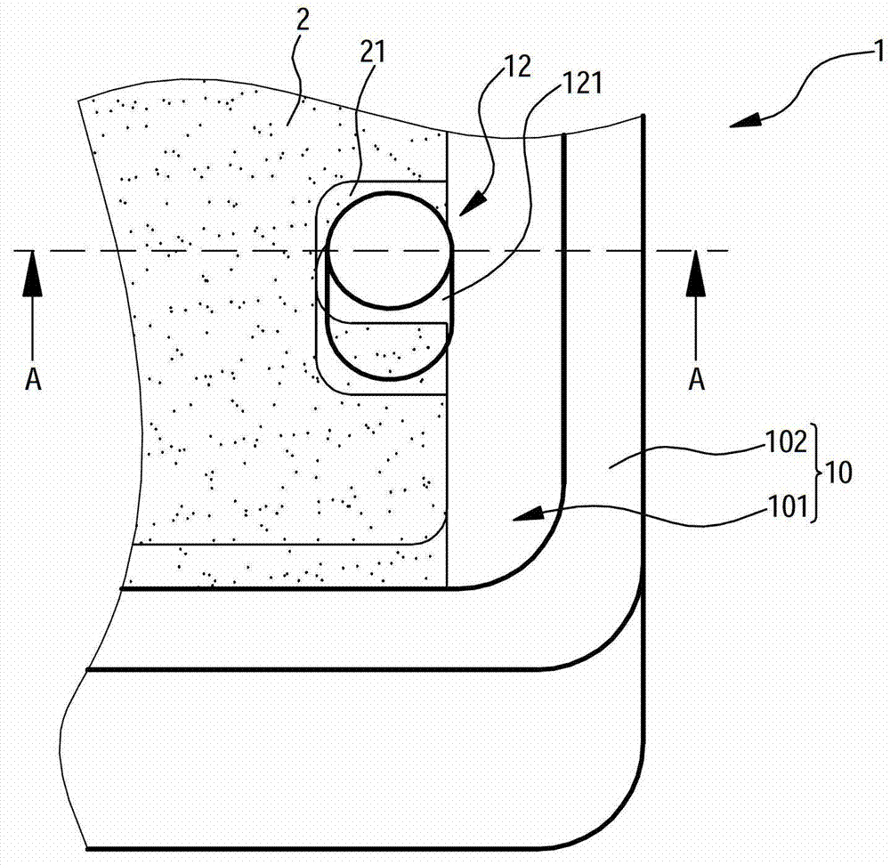
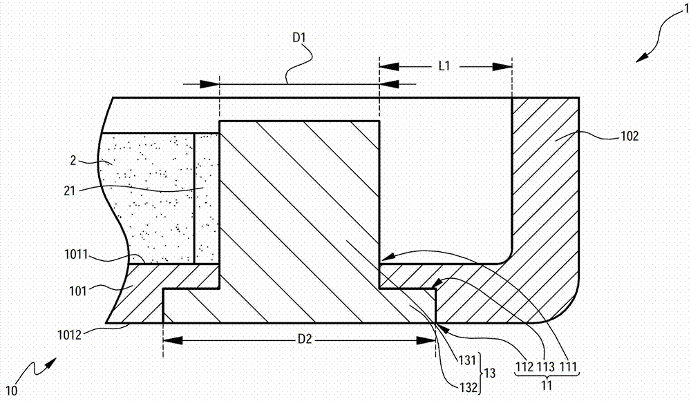
If the distance L1 from the column portion 121 to the upright side 102 cannot be reduced, the maximum viewing area of ​​the optical unit 2 cannot be enlarged, that is, the frame thickness of the liquid crystal display cannot be narrowed.

Method used


Image

  • Back plate component and liquid crystal display
  • Back plate component and liquid crystal display
  • Back plate component and liquid crystal display

Examples


Embodiment Construction

[0033] Further details will be given below in conjunction with the embodiments shown in the accompanying drawings.

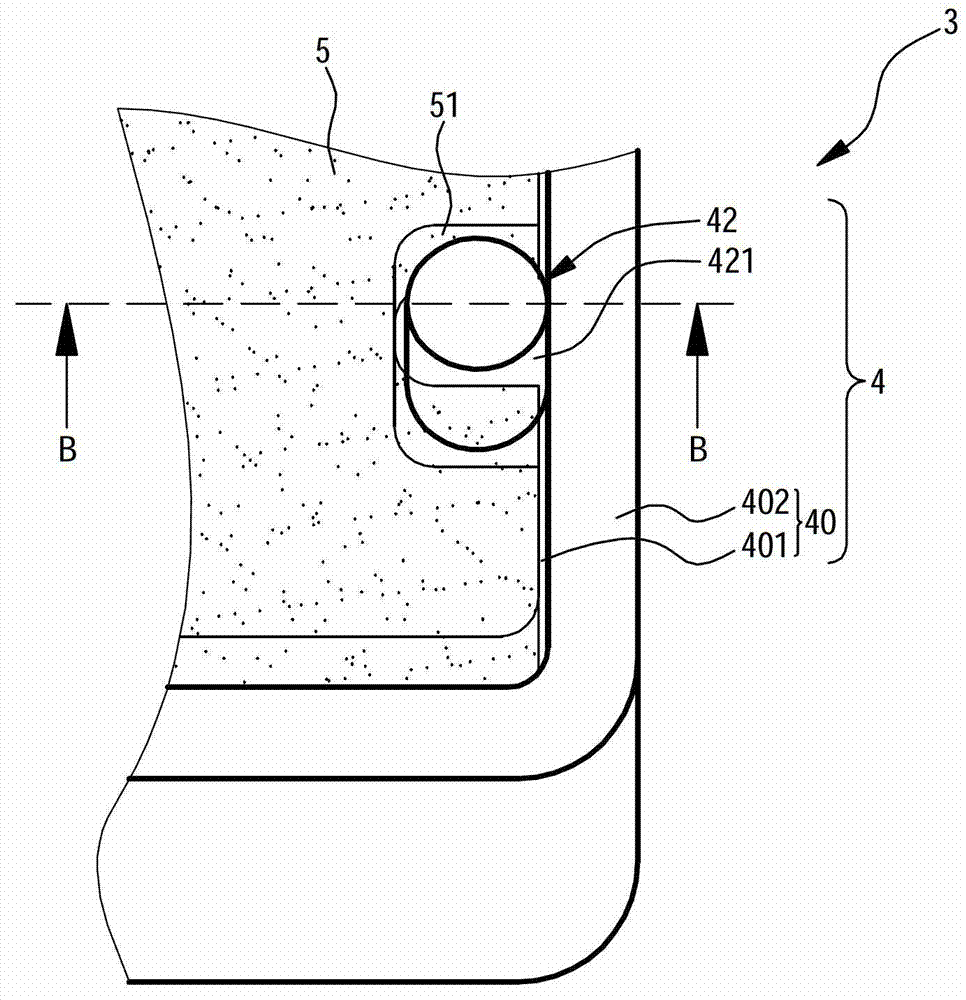
[0034] Please also refer to image 3 and Figure 4 , image 3 It is a structural diagram of a backplane assembly 4 of the present invention. Figure 4 It is an enlarged cross-sectional view of the backplane assembly 4 of the present invention along the section line BB.

[0035] The figure shows a partial structure of a backlight module 3 , the backlight module 3 includes: a backplane assembly 4 and an optical unit 5 . Firstly, the back plate assembly 4 is suitable for accommodating and positioning the optical unit 5 , and the back plate assembly 4 includes: a back plate 40 , a plurality of tapered holes 41 and a plurality of optical unit positioning posts 42 .

[0036] The backboard 40 includes: a plate 401 and an upright side 402 . The board 401 has a first surface 4011 and a second surface 4012 , and the second surface 4012 is opposite to the first surfac...


PUM


Abstract

A back plate component applicable to holding and positioning an optic unit comprises a back plate, a plurality of taper holes, and a plurality of optic unit positioning columns. The back plate comprises a plate and a stand side edge which surrounds the plate and is perpendicular to the same. The plate is provided with a first surface and an opposite second surface. The taper holes are formed on the back plate, each taper hole is provided with a first opening and a second opening, the first openings are formed on the first surface, the second openings are formed on the second surface, and the first openings are smaller than the second openings. Each of the optic unit positioning columns is provided with a column body portion and an annular head at one end of the column body portion. The outer diameter of each annular head is smaller than the diameter of each column body portion. The annular heads of the optic unit positioning columns respectively penetrate through the taper holes via the first openings, deform and expand outwards by the aid of external force so as to abut against the taper holes tightly, and then the optic unit positioning columns are enabled to be fixed on the back plate. The outer diameter of each of the deformed and expanded annular heads is still smaller than the diameter of each of the column body portions, and effect of a narrow-border display can be achieved by enabling the distance between the column body parts and the stand side edge to be approachable to zero.

Description

technical field [0001] The present invention relates to a back panel assembly and a liquid crystal display, in particular to a back panel assembly and a liquid crystal display which achieve a narrow frame effect by making the distance between the positioning column of the optical unit and the side of the back panel close to zero. Background technique [0002] In the field of liquid crystal displays, it is a future trend that the frame of the display becomes smaller and smaller. Therefore, in the production process of the backlight module of the display, it is even more important how to maximize the visible area of ​​the backlight module and minimize the frame of the backlight module. In an edge-lit backlight module, a light guide plate is an important optical component. The positioning method of the light guide plate will also affect the thickness of the frame of the liquid crystal display. Generally speaking, the optical unit positioning post is a common light guide plate...

Claims


Application Information

Patent Timeline
Patent Type & Authority Applications(China)
IPC IPC(8): F21V21/00F21V17/12G02F1/13357
CPCG02B6/0088G02F1/133608H05K7/18
Inventor 俞刚杨熙
Owner TCL CHINA STAR OPTOELECTRONICS TECH CO LTD
Learn More