Array substrate, display panel and display device

An array substrate and display area technology, which is applied to static indicators, semiconductor/solid-state device parts, instruments, etc., can solve problems such as unfavorable narrow borders and large width of the non-display area of ​​the array substrate, so as to reduce the production yield, The effect of improving process requirements

Active Publication Date: 2020-03-06
XIAMEN TIANMA MICRO ELECTRONICS
View PDF3 Cites 0 Cited by
  • Summary
  • Abstract
  • Description
  • Claims
  • Application Information

AI Technical Summary

Problems solved by technology

[0005] Embodiments of the present invention provide an array substrate, a display panel, and a display device, which are used to solve the problem in the prior art that the non-display area of ​​the array substrate has a large width and is not conducive to narrow borders.

Method used


Image

  • Array substrate, display panel and display device
  • Array substrate, display panel and display device
  • Array substrate, display panel and display device

Examples


Embodiment Construction

[0022] The specific implementation manners of the array substrate, the display panel and the display device provided by the embodiments of the present invention will be described in detail below with reference to the accompanying drawings.

[0023] The shapes and sizes of the elements in the drawings do not reflect the real proportion of the array substrate, but are only intended to schematically illustrate the content of the present invention.

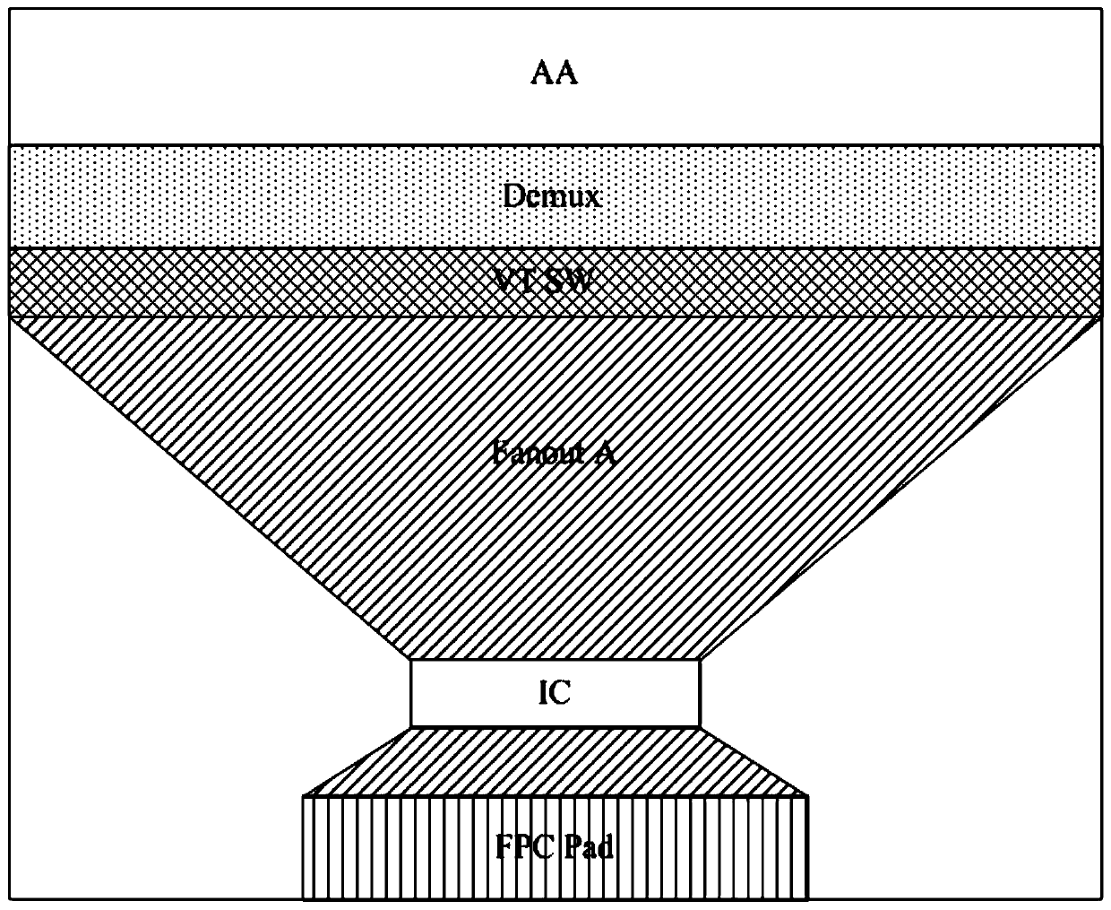
[0024] Currently, in some display array substrates, at one side of the non-display area such as the lower frame (border), such as Figure 1a As shown, it generally includes: demultiplexer component Demux, test switch component VT SW, data signal sector trace Fanout A, driver chip IC and flexible circuit board pad FPC Pad and other components.

[0025] At the lower frame, from the display area to the outer edge, the demux component Demux, the test switch component VT SW, the data signal sector trace Fanout A, the driver chip IC and the ...


PUM


Abstract

The invention discloses an array substrate, a display panel and a display device. The array substrate includes: a plurality of data lines arranged in a display area, a demultiplexer assembly, a test switch assembly and a plurality of data signals respectively arranged in a non-display area sector wiring; the signal output end of the demultiplexer assembly is connected to the data line, and the input end of the demultiplexer assembly is respectively connected to the data signal sector wiring and the output end of the test switch assembly; the test switch assembly is arranged in multiple The side of the road divider component away from the display area. By changing the plurality of data signal sector lines and test switch components arranged in the non-display area to different layers, so that they have an overlapping area, so as to change the order in which the elements in the non-display area of ​​the current array substrate are continuously arranged, Therefore, while maintaining the performance and size of the components at the original lower frame, the width of the non-display area is compressed, and the effect of a narrow frame can be achieved without increasing process requirements and reducing production yield.

Description

technical field [0001] The invention relates to the field of display technology, in particular to an array substrate, a display panel and a display device. Background technique [0002] In order to improve the display effect of the display device, more and more people begin to pay attention to the narrow bezel design of the display device, especially for the splicing screen used for large-screen outdoor display, the narrow bezel display device can effectively reduce the splicing in the splicing screen. The width of the seam significantly improves the overall display effect. [0003] In the prior art, the production of narrow-frame displays is usually done by compressing the size of the components at the frame, which not only limits the compression ratio, but also increases the requirements of the process, reduces the production yield, and at the same time, the performance of the product will also be affected to a certain extent. [0004] Therefore, how to compress the width...

Claims


Application Information

Patent Timeline
Patent Type & Authority Patents(China)
IPC IPC(8): H01L27/12H01L23/544
CPCH01L22/30H01L27/124G02F1/13452G02F1/13454G02F1/13456G09G3/006G09G3/20G09G2310/0297
Inventor 周洪波
Owner XIAMEN TIANMA MICRO ELECTRONICS
Why Eureka
Try Eureka