Backlight module, display panel and preparation method of backlight module

A backlight module, one-sided technology, applied in optics, nonlinear optics, identification devices, etc., can solve problems such as unstable quality of backlight modules

Pending Publication Date: 2021-01-19
K TRONICS (SUZHOU) TECH CO LTD +1
View PDF16 Cites 0 Cited by
  • Summary
  • Abstract
  • Description
  • Claims
  • Application Information

AI Technical Summary

Problems solved by technology

[0004] The present invention provides a display device to solve the problem of unstable quality of the backlight module caused by the existing backlight source in order to achieve the effect of narrow frame and ultra-thin

Method used


Image

  • Backlight module, display panel and preparation method of backlight module
  • Backlight module, display panel and preparation method of backlight module
  • Backlight module, display panel and preparation method of backlight module

Examples


Embodiment 1

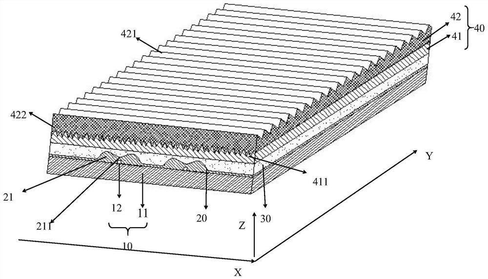
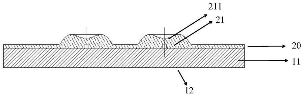
[0051] refer to figure 2 , shows a backlight module, the present invention provides a backlight module in one aspect, the backlight module includes: a lamp board 10 and a plurality of adhesive layers stacked on the lamp board 10, the lamp The board includes a substrate 11 and a plurality of point light sources 12 distributed on the substrate 11, and the plurality of adhesive layers include:

[0052] a light-scattering layer 20 covering the plurality of point light sources 12;

[0053] a diffusion layer 30 coated on the side of the light scattering layer 20 facing away from the lamp panel 10;

[0054]The correction layer 40 coated on the side of the diffusion layer 30 away from the light-scattering layer 20, the correction layer 40 is used to correct the light output by the diffusion layer 30 toward the normal direction of the light exit surface of the correction layer 40.

[0055] In the embodiment of the present invention, the function of the lamp board is mainly to arrang...

Embodiment 2

[0084] refer to Figure 12 , showing a flow chart of the steps of a method for preparing a backlight module provided by an embodiment of the present invention; the method specifically includes the following steps:

[0085] Another aspect of the present invention is to provide a method for preparing a backlight module, including:

[0086] Step 201, provide a lamp board, the lamp board includes: a substrate and a plurality of point light sources distributed on the substrate.

[0087] Among them, the function of the lamp board is mainly to arrange lamps, and the substrate serves as the carrier of the entire point light source.

[0088] Wherein, preparing a plurality of adhesive layers on the lamp panel specifically includes the following steps:

[0089] Step 202, coating a light-scattering layer on the lamp panel so that the light-scattering layer covers the multiple point light sources.

[0090] In the embodiment of the present invention, the light-scattering layer mainly exp...


PUM


Abstract

The embodiment of the invention provides a backlight module, a display panel and a preparation method of the backlight module, the backlight module comprises a lamp panel and a plurality of adhesive layers arranged on the lamp panel in a stacked mode, and the lamp panel comprises a substrate and a plurality of point light sources distributed on the substrate. The plurality of adhesive layers comprise a light scattering layer covering the plurality of point light sources; a diffusion layer which coats one surface, deviating from the lamp panel, of the light scattering layer; and a correction layer which coats one surface, deviating from the light scattering layer, of the diffusion layer, and is used for correcting the light output by the diffusion layer towards the normal direction of the light emitting surface of the correction layer. According to the embodiment of the invention, the plurality of optical adhesive layers are arranged on one side of the lamp panel, so that the backlightmodule is thinned on the premise of not influencing the quality of the backlight module, and the effects of high brightness and narrow frame are achieved.

Description

technical field [0001] The invention relates to the field of display technology, in particular to a backlight module, a display panel and a method for preparing the backlight module. Background technique [0002] With the development of science and technology, the requirements for backlight products are getting higher and higher; it is the current mainstream to require backlights to be ultra-thin, bright, and narrow bezel. For the design of the ultra-thin and narrow frame of the backlight, various new methods are emerging in an endless stream. In the existing technology, the backlight needs to be ultra-thin, which is based on the existing structure to reduce the thickness of the components used. The narrow frame of the backlight is all It is based on continuously reducing the adhesive width of the tape. [0003] refer to figure 1 , is a backlight source in the prior art, including light-shielding glue a2, upper prism b2, lower prism c2, diffusion d2, light board e2, and fr...

Claims


Application Information

Patent Timeline
Patent Type & Authority Applications(China)
IPC IPC(8): G09F9/00G02F1/13357
CPCG09F9/00G02F1/133606
Inventor 夏小丽
Owner K TRONICS (SUZHOU) TECH CO LTD
Why Eureka
Try Eureka