Infrared touch device and profile

An infrared touch and infrared technology, applied in radiation control devices, instruments, electrical digital data processing, etc., can solve problems such as prone to false touches, large frame width, and large distance between touch areas, so as to reduce the possibility of false touches , reduce width and thickness, and improve user experience

Active Publication Date: 2020-09-11
SHENZHEN HONGHE INNOVATION INFORMATION TECH CO LTD +1
View PDF4 Cites 0 Cited by
  • Summary
  • Abstract
  • Description
  • Claims
  • Application Information

AI Technical Summary

Problems solved by technology

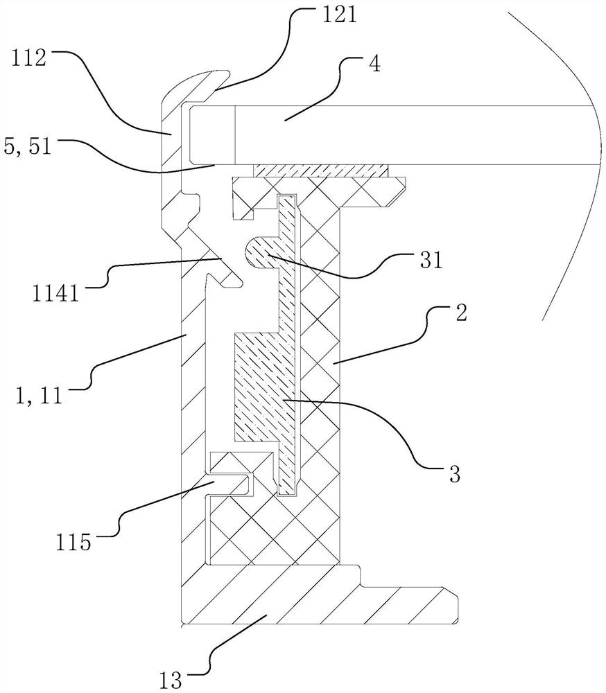
In the infrared touch device of the above type, there is at least a dimension of the wall thickness of the profile between the filter strip and the front surface of the frame, and between the filter strip and the panel, which makes the front surface of the frame of the infrared touch device higher than the panel. The size, which is at least equal to the width of the filter bar plus twice the thickness of the profile, results in a thicker frame and a larger distance between the tou

Method used


Image

  • Infrared touch device and profile
  • Infrared touch device and profile
  • Infrared touch device and profile

Examples


Embodiment Construction

[0029] The present invention is described below based on examples, but the present invention is not limited to these examples. In the following detailed description of the present invention, some specific details are described in detail, and in order to avoid obscuring the essence of the present invention, known methods, procedures, procedures, and components are not described in detail.

[0030] Additionally, those of ordinary skill in the art will appreciate that the drawings provided herein are for illustrative purposes and are not necessarily drawn to scale.

[0031] Unless the context clearly requires, throughout the specification and claims, "comprises", "comprises" and similar words should be interpreted in an inclusive sense rather than an exclusive or exhaustive meaning; that is, "including but not limited to" meaning.

[0032]In the description of the present invention, it should be understood that the terms "first", "second" and so on are used for descriptive purpo...


PUM


Abstract

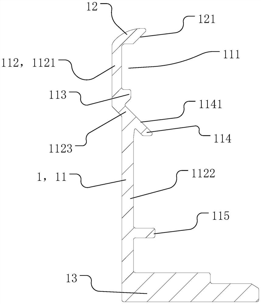
The invention provides an infrared touch device and a profile. The device comprises an infrared board card, a light filtering part, a panel and an outer frame, the outer frame comprises a side frame part, a front frame part connected with the front end of the side frame part, and a rear frame part connected with the rear end of the side frame part. The side frame part comprises a panel accommodating groove for accommodating the edge part of the panel; a first side wall of the panel accommodating groove is formed on the rear side surface of the front frame part; the end surface of the free endof the front frame part is a first inclined surface; the first slope and the first side wall form an obtuse angle; the first inclined surface forms a first reflecting surface; or a first reflecting layer is arranged on the first inclined surface, a first reflecting surface is formed on the outer surface of the first reflecting layer, and at least part of infrared light emitted by the infrared board card sequentially penetrates through the light filtering part and the panel and is reflected by the first reflecting surface into light which is located on the front side of the panel and propagatesin the direction parallel to the front side surface of the panel; and the light filtering part is arranged on the rear side of the panel, so that the effects of a narrow frame and a thin frame are better achieved, and the risk that the light filtering part falls off is also reduced.

Description

technical field [0001] The invention relates to the technical field of infrared touch, in particular to an infrared touch device and a profile. Background technique [0002] Existing touch screens generally use infrared touch, and the infrared boards (PCBAs) of the current infrared touch solutions are designed to be placed horizontally or vertically, and the infrared touch circuit board components and the filter strips are fixed to the frame. Due to the layout of the infrared touch circuit board components and the filter strips, the frame will inevitably be wider and thicker. In the existing installation method, both the front side and the rear side of the filter strip need to be fixedly connected with the frame, which leads to a larger distance between the filter strip and the display screen, making the height of the touch area basically greater than 3mm, which means When the touch object is 3mm away from the front side of the display, the touch will respond, which is pron...

Claims


Application Information

Patent Timeline
IPC IPC(8): G06F3/042
CPCG06F3/0421G06F3/0428H01L23/04H01L27/144
Inventor 陈廷峰刘欣逸
Owner SHENZHEN HONGHE INNOVATION INFORMATION TECH CO LTD
Why Eureka
Try Eureka