
Rapid inspection method and rapid inspection system for bridge bottom damage positions

A rapid inspection and bridge technology, applied in the direction of measuring devices, optical devices, instruments, etc., can solve problems such as poor accuracy, difficult to use, and photo deformation, and achieve the effect of easy manufacturing, simple structure, and high accuracy

Active Publication Date: 2012-12-19
GUANGZHOU MUNICIPAL ENG DESIGN & RES INST CO LTD
View PDF5 Cites 14 Cited by
  • Summary
  • Abstract
  • Description
  • Claims
  • Application Information

AI Technical Summary

Problems solved by technology

However, the system has several disadvantages
First of all, the safety is not good. Instruments weighing tens of kilograms are suspended from the side of the bridge. Even if many safety measures are taken, the risk of falling from a high altitude cannot be completely ruled out. The bridge is difficult to use; third, the accuracy is poor, because the fulcrum is on the railing, for the bridge with a certain arc in the longitudinal direction of the bottom of the beam, the support is not perpendicular to the axis of the bottom of the beam, and the fulcrum and the observation platform are relative to the longitudinal direction of the beam. The position is not consistent, which will produce a large initial deviation; fourth, because the bottom of the bridge is observed from the side, the vertical observation angle is very small, and it is basically impossible to measure the damage extending parallel to the observation direction at a far distance. The size of the photos taken is also greatly deformed; Fifth, for the "T" beam bridge, the line of sight is obstructed, and only the first beam on the outermost side can be observed, while the secondary side beams and other intermediate beams will not be observed. arrive

Method used


Image

  • Rapid inspection method and rapid inspection system for bridge bottom damage positions
  • Rapid inspection method and rapid inspection system for bridge bottom damage positions

Examples


Embodiment Construction

[0035] The concept, specific structure and technical effects of the present invention will be clearly and completely described below in conjunction with the embodiments and accompanying drawings, so as to fully understand the purpose, features and effects of the present invention. Apparently, the described embodiments are only some of the embodiments of the present invention, rather than all of them. Based on the embodiments of the present invention, other embodiments obtained by those skilled in the art without creative efforts belong to The protection scope of the present invention. In addition, all the connection / connection relationships mentioned in this article do not refer to the direct connection of components, but mean that a better connection structure can be formed by adding or reducing connection accessories according to specific implementation conditions.

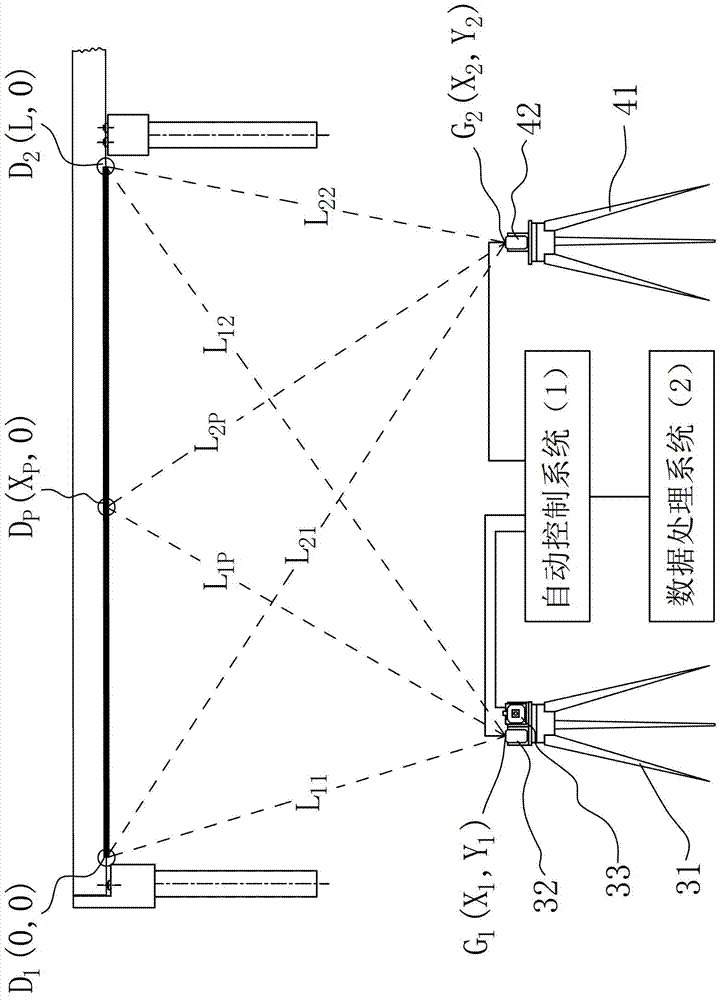
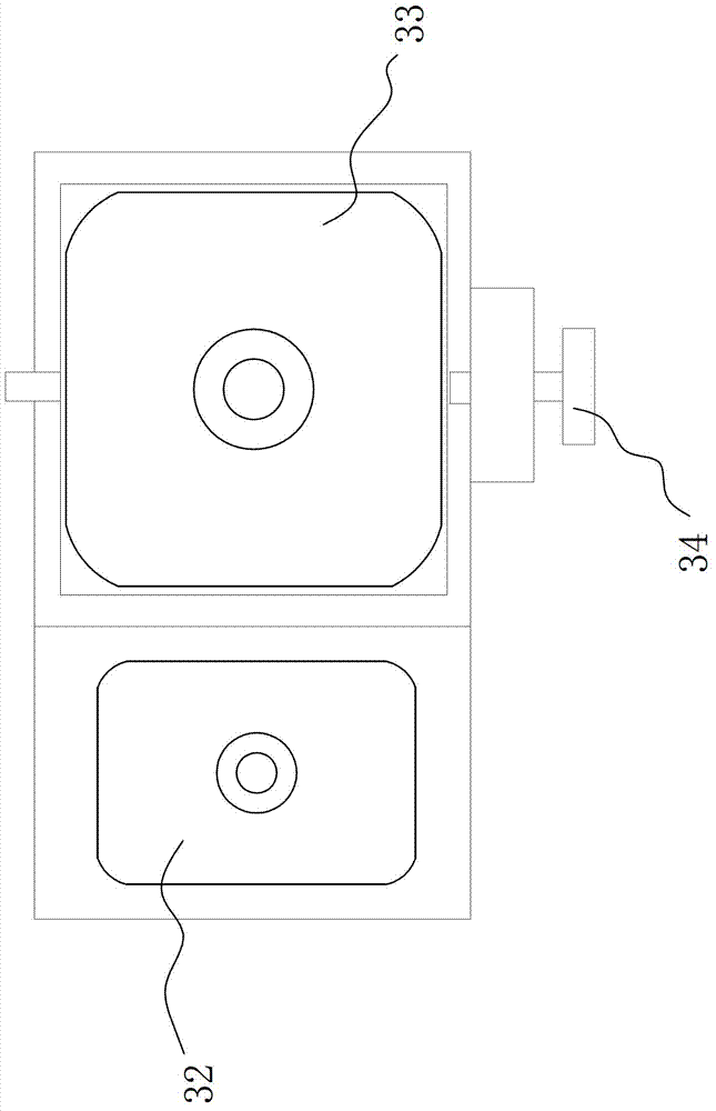
[0036] refer to Figure 1 ~ Figure 2 , at first make the rapid inspection system for the damaged position at...


PUM


Abstract

The invention discloses a rapid inspection method for bridge bottom damage positions. The method includes the steps: determining a left observation point and a right observation point at the bridge bottom, and determining a left initial measurement point and a right initial measurement point on the bridge axis; respectively measuring relative distances among different observation points and different initial measurement points; measuring the relative distances among different observation points and damage points; and computing the damage point positions according to all measurement results. The invention further discloses a rapid inspection system for the bridge bottom damage positions, and the system is capable of realizing the inspection method. The method adopting underbridge indirect measurement is easy, feasible, accurate in measurement results and simple and rapid in operation and the inspection system is simple and easy to operate and can be applied to bridge bottom damage inspection.

Description

technical field [0001] The invention relates to an engineering detection technology and a detection device, in particular to a method and system for inspecting and measuring the damaged position of the bottom of a bridge girder. Background technique [0002] The main tasks of bridge damage inspection include: determining the type of damage; determining the location of the damage; measuring the size of the damage; taking pictures of the damage location. Among them, determining the type of damage can only be determined by manual judgment, which can be confirmed by visual inspection or viewing photos. Therefore, the bridge damage inspection system should have the functions of damage location, measurement and photographing. [0003] In bridge damage inspection, the inspection of beam bottom damage is one of the difficulties. Bridges with a height of less than 5m are relatively easy to manage. After driving under the bridge, people can go up to the roof to inspect, measure and ...

Claims


Application Information

Patent Timeline
IPC IPC(8): G01C11/00G01C3/02G01B11/02
Inventor 彭功勋刘菊玖胡晓勇陶华飞徐鲁华
Owner GUANGZHOU MUNICIPAL ENG DESIGN & RES INST CO LTD
Learn More