Long-focus transmission-type quasi telecentric three-linear-array stereoscopic mapping optical system

An optical system, stereo mapping technology, applied in optics, optical components, instruments, etc., can solve the problem that there is no precedent for the successful application of long focal length transmissive systems, and can reduce the confocal accuracy, ensure the processing accuracy, and evenly distribute the centroid. Effect

Active Publication Date: 2014-11-19
BEIJING RES INST OF SPATIAL MECHANICAL & ELECTRICAL TECH
View PDF2 Cites 0 Cited by
  • Summary
  • Abstract
  • Description
  • Claims
  • Application Information

AI Technical Summary

Problems solved by technology

[0005] The optical systems of surveying and mapping cameras that have been put into use at present adopt the transmissive structure type, all of which are short-focus optical systems, and there is no precedent for the successful application of long-focus transmissive systems.

Method used


Image

  • Long-focus transmission-type quasi telecentric three-linear-array stereoscopic mapping optical system
  • Long-focus transmission-type quasi telecentric three-linear-array stereoscopic mapping optical system
  • Long-focus transmission-type quasi telecentric three-linear-array stereoscopic mapping optical system

Examples


Embodiment

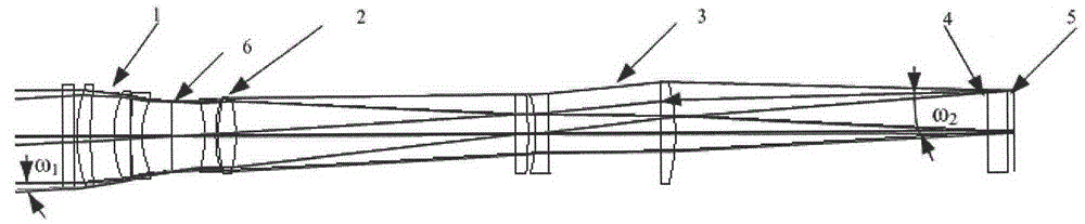
[0039] An embodiment of the optical system of the present invention has a focal length of 1700 (front view) / 1750 mm (front view and rear view), and the working spectrum is 500-800 nm in the visible spectrum. Based on the requirements of camera system energy and signal-to-noise ratio, the relative aperture of the sub-optical system Selected as 1 / 8.5, the effective field of view is 6°, that is, ω1 is 3°, the angle of the edge chief ray incident on the image plane is compressed from 3° to 1.5°, and the angular magnification of the optical system is "=0.5; the dimensions of the sub-optical system It is Φ225mm×1850mm, of which the anti-radiation window 7 has the largest aperture, which is Φ225mm; the maximum light aperture of the front lens group 1, the middle lens group 2 and the rear lens group 3 appears in the first meniscus positive lens of the front lens group 1, which is Φ220mm, the total lateral length of the eight lenses is 1150mm.

[0040] The minimum pixel size of the rec...


PUM

PropertyMeasurementUnit
thicknessaaaaaaaaaa

Abstract

The invention relates to a long-focus transmission-type quasi telecentric three-linear-array stereoscopic mapping optical system. The long-focus transmission-type quasi telecentric three-linear-array stereoscopic mapping optical system comprises three optical subsystems with completely consistent structure forms, wherein each optical subsystem comprises a front lens group (1), a diaphragm (6), a middle lens group (2), a rear lens group (3), a transflective prism (4) and a receiving image surface (5), all of which are sequentially arranged along the light ray incidence direction, the caliber of a radiation beam of a mapping target is regulated after the radiation beam passes through the front lens group (1), the radiation beam is full of the diaphragm (6) to exit, an angle amplification ratio is regulated after the outgoing beam passes through the middle lens group (2) and the rear lens group (3), and the outgoing beam exits to the transflective prism (4), so that the outgoing beam is divided and then is imaged on the receiving image surface (5). The optical system disclosed by the invention has the advantages of long-focus transmission type, quasi telecentricity, zero distortion, good stability of element of interior orientation, high optical machine structure integration degree and the like, and can realize higher-proportion stable mapping function in the terrain and the geomorphology of a target scene through the reasonable arrangement of a front-vision camera, a positive-vision camera and a back-vision camera.

Description

technical field [0001] The invention belongs to the technical field of space optical remote sensors, and relates to an optical imaging system applied to a space three-line array three-dimensional surveying and mapping camera. Background technique [0002] The main task of the surveying and mapping camera is to take stereoscopic photography of the earth's surface, obtain multi-dimensional image data of ground objects, use surveying and mapping processing technology to process the image data, and accurately measure the topography, ground object shape, size, attribute and spatial position information. There are many ways to achieve stereoscopic imaging, such as single-lens three-line array, single-line array on the same track, single-line array on different track, double-line array on the same track, three-lens three-line array, etc. Each method has its own characteristics, and the accuracy of the stereoscopic image It is also different, and the requirements for the stability o...

Claims


Application Information

Patent Timeline
Patent Type & Authority Patents(China)
IPC IPC(8): G01C11/02G02B27/22G02B1/11
Inventor 汤天瑾周峰黄颖兰丽艳高卫军王长杰朱永红孙立
Owner BEIJING RES INST OF SPATIAL MECHANICAL & ELECTRICAL TECH
Why Eureka
Try Eureka