Supercharge Your Innovation With Domain-Expert AI Agents!

Multi-circle code converter based on mechanical gear set circle count

An encoder converter and gear set technology, which is applied in the direction of using optical devices to transmit sensing components, etc., can solve the problems of inaccurate memory number of turns, inability to remember the number of turns, limiting the application range of multi-turn absolute rotary encoders, etc., to achieve accurate The effect of memory laps

Active Publication Date: 2012-12-19
连云港杰瑞电子有限公司
View PDF5 Cites 3 Cited by
  • Summary
  • Abstract
  • Description
  • Claims
  • Application Information

AI Technical Summary

Problems solved by technology

[0005] The multi-turn encoding conversion circuit is the key technology of the multi-turn absolute rotary encoder. It is an encoding circuit that increases the number of turns on the basis of single-turn encoding to expand the measurement range of the rotary encoder and enable each position of the rotary encoder to achieve encoding. Uniqueness and non-repetition. At present, domestic multi-turn code conversion circuits mostly use electronic data memory to count the number of turns. The number of turns is calculated by software, and the number of turns is memorized by the memory. The advantage of this method is that it is simple to store the number of turns, and the number of turns can be unlimited. , the information at the time of power failure can be restored after power failure, but the disadvantage is also obvious. It cannot memorize the number of laps after power failure.
There are also a small number of manufacturers in China that use mechanical counting of the number of turns. Due to the limitation of the size of the rotary encoder and the technical level, generally only 8 digits of the number of turns can be memorized at most.
Therefore, this greatly limits the application range of multi-turn absolute rotary encoders

Method used


Image

  • Multi-circle code converter based on mechanical gear set circle count
  • Multi-circle code converter based on mechanical gear set circle count
  • Multi-circle code converter based on mechanical gear set circle count

Examples


Embodiment Construction

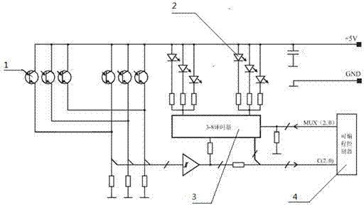
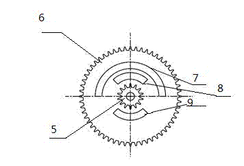
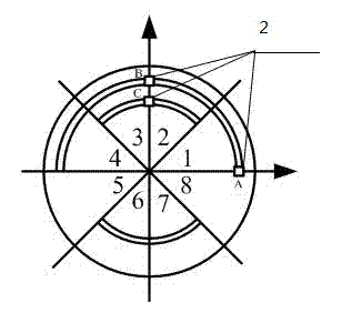
[0021] A multi-turn code converter based on the number of turns of a mechanical gear set, including a programmable controller 4 and 1 to 8 groups of photoelectric conversion mechanisms, each group of photoelectric conversion mechanisms includes an intermediate transmission gear, three light-emitting diodes 2 and light-emitting diodes The three phototransistors 1 corresponding to the diodes one by one, the light emitting diode 2 and the phototransistor 1 are respectively arranged on both sides of the intermediate transmission gear, and there is a light-transmitting groove on the intermediate transmission gear. The light-transmitting groove includes an inner ring groove and an outer ring arranged concentrically. The inner ring groove is a 90° fan-shaped groove 8,9 arranged symmetrically in two sections, the outer ring groove is a 180° semicircular groove 7, the center of the inner ring groove on the same side of the outer ring groove and the center of the outer ring groove and Th...


PUM


Abstract

A multi-circle code converter based on mechanical gear set circle count comprises a gear, light emitting diodes and a phototransistor circuit. A gear set is driven by the gear according to the watch gear mechanical principle to realize conversion from mechanical signals to electric signals by means of photoelectric conversion. A programmable controller sends a control signal MUX (2..0), one to eight light emitting diode groups are controlled to be lightened through three to eight decoder circuits, light permeable slots in uniformly distribution are reserved on an intermediate transmission gear and capable of blocking off or allowing light irradiation, phototransistors receive the light to sense eight different states and output one to eight groups of signals C (2..0), the signals are processed through the programmable controller, and two to sixteen bit binary gray code multi-circle code signals are outputted by means of cascading after signal error correction is completed by a logic circuit. Since mechanical positions are used for determining codes, circle numbers can be accurately memorized without outage influences.

Description

technical field [0001] The invention relates to the technical field of electromechanical integration, in particular to a multi-turn encoder converter based on counting the number of turns of a mechanical gear set. Background technique [0002] Rotary encoders are sensors used to detect angle, position, speed and acceleration. They are suitable for various automatic control systems and are mainly used in elevators, CNC machine tools, machinery, electric power, water conservancy, rail transit, wind power, radar, satellites and other fields. [0003] The technical advantages of rotary encoders are concentrated in Europe and the United States where the industry is developed, and Germany is the first to promote. The rotary encoders of its brands such as Heidenhain and Pepperl+Fuchs occupy most of the high-end market. The products are mainly multi-turn rotary encoders. Japan and South Korea mainly produce small rotary encoders. Domestic manufacturers are limited to manufacturing a...

Claims


Application Information

Patent Timeline
Patent Type & Authority Applications(China)
IPC IPC(8): G01D5/34
Inventor 高文政韩彬徐磊
Owner 连云港杰瑞电子有限公司
Features
  • R&D
  • Intellectual Property
  • Life Sciences
  • Materials
  • Tech Scout
  • Unparalleled Data Quality
  • Higher Quality Content
  • 60% Fewer Hallucinations
Learn More