Distributed fault location method for T-circuit

A fault distance measurement and distributed technology, applied in the direction of fault location, etc., can solve the problem that the fault branch cannot be correctly and effectively judged, and achieve the effect of improving the distance measurement accuracy, simplifying the algorithm, and having a good application prospect

Active Publication Date: 2012-12-19
SHANGHAI JIAO TONG UNIV +1
View PDF4 Cites 30 Cited by
  • Summary
  • Abstract
  • Description
  • Claims
  • Application Information

AI Technical Summary

Problems solved by technology

Due to the influence of the transient process or the influence of the GPS synchronization error, the existi

Method used


Image

  • Distributed fault location method for T-circuit
  • Distributed fault location method for T-circuit
  • Distributed fault location method for T-circuit

Examples


Embodiment Construction

[0032] Below in conjunction with the drawings, preferred embodiments of the present invention are given and described in detail.

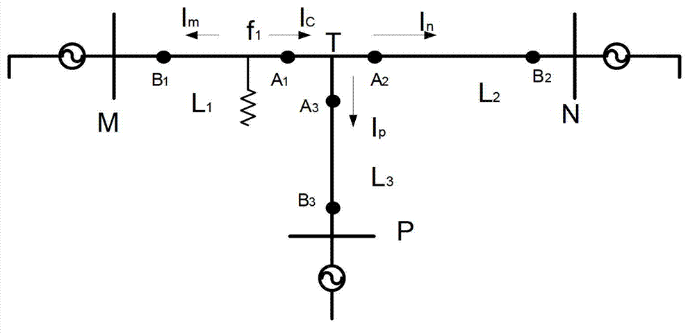
[0033] See 2, figure 2 It is the installation distribution diagram of the fault current detection device in the T-shaped circuit of the present invention. As shown in the figure, two Rogowski coils are installed on each branch in the T-shaped circuit as the fault current detection device, respectively A 1 , B 1 、A 2 , B 2 、A 3 , B 3 , where A 1 、A 2 、A 3 For the first group of fault current detection devices, they are the same distance from T node, B 1 , B 2 , B 3 They are respectively located on the three branches MT, NT and PT of the T-shaped line, and take the center point of each branch as the symmetrical point and A 1 、A 2 、A 3 Relatively symmetrical position, i.e. MB 1 、TA 1 、TA 2 , NB 2 、TA 3 , PB 3 The distance is Y. The wave impedance of each transmission line is Z. Since the distance measurement method is the same whe...


PUM


Abstract

The invention discloses a distributed fault location method for a T-circuit. At least two fault current detectors are installed on each branch of the T-circuit. Each fault current detector is connected with a monitoring master station through a remote wireless communication module. The monitoring master station analyzes fault current information according to stored algorithm, judges a faulted branch according to travelling wave energy, and further analyzes to judge fault section according to arrival time series of fault current travelling energy detected by the two fault current detectors on the faulted branch, and calculates the fault location according to a positioning equation. The method solves the problem that a dead zone occurs when a fault point is close to a T node and is high in positioning precision.

Description

technical field [0001] The invention relates to a T-shaped high-voltage transmission line, in particular to a method for distributed fault distance measurement of a T-shaped line. Background technique [0002] T-shaped lines are widely used in power systems due to their simple wiring, fast construction speed, effective reduction of equipment investment, and saving of line corridors. Therefore, the research on high-precision T-type line fault location method can greatly shorten the fault recovery time. [0003] After a fault occurs on a high-voltage transmission line, a fault current traveling wave running to both ends will be generated at the fault point. When the fault current traveling wave encounters an inhomogeneous medium during propagation, refraction and reflection will occur. For the fault current traveling wave, its refraction coefficient α is: [0004] a = 2 Z 1 ...

Claims


Application Information

Patent Timeline
IPC IPC(8): G01R31/08
Inventor 申文盛戈皞刘亚东孙旭日江秀臣
Owner SHANGHAI JIAO TONG UNIV
Why Eureka
Try Eureka