Display apparatus

A technology for display equipment and image display devices, applied in optical components, optics, instruments, etc., can solve the problem that observers cannot fully contrast images, achieve high contrast, reduce power consumption, and increase the amount of external light

Inactive Publication Date: 2012-12-19
SONY CORP
View PDF15 Cites 41 Cited by
  • Summary
  • Abstract
  • Description
  • Claims
  • Application Information

AI Technical Summary

Problems solved by technology

[0008] However, in the case where the surrounding environment where the image display device 100' or 300' is installed is very bright, or depending on the content of the displayed image, there may be a problem that the observer cannot give sufficient contrast to the viewed image.

Method used


Image

  • Display apparatus
  • Display apparatus
  • Display apparatus

Examples


no. 1 approach

[0061] 2. First Embodiment (Display Device According to the Present Disclosure)

[0062] 3. Second Embodiment (First Modification of First Embodiment)

[0063] 4. Third Embodiment (Second Modification of First Embodiment)

[0064] 5. Fourth Embodiment (Third Modification of First Embodiment)

[0065] 6. Fifth Embodiment (Fourth Modification of First Embodiment)

[0066] 7. Sixth Embodiment (Fifth Modification of First Embodiment)

[0067] 8. Seventh Embodiment (Sixth Modification of First Embodiment)

[0068] 9. Eighth Embodiment (Display Device 1A to Display Device 1B According to the Present Disclosure)

[0069] 10. Ninth Embodiment (Display Device 1C According to the Present Disclosure)

[0070] 11. Tenth Embodiment (Modification of Eighth Embodiment and Ninth Embodiment)

[0071] 12. Eleventh Embodiment (Modification of Tenth Embodiment)

[0072] 13. Twelfth Embodiment (Display Device 3A According to the Present Disclosure)

[0073] 14. Thirteenth Embo...

no. 2 approach

[0207] The second embodiment is a modified example of the first embodiment. Figure 5 is a conceptual diagram showing the image display device 200 in the display device (head-mounted display) according to the second embodiment. In the second embodiment, the image forming device 211 includes the image forming device of the second configuration. That is, the image forming apparatus 211 includes a light source 251 and a scanning unit 253 that scans the parallel light emitted by the light source 251 . More specifically, the image forming device 211 includes (i) a light source 251, (ii) a collimating optical system 252 that collimates the light output by the light source 251 into parallel light, (iii) a scanning unit 253 that scans The light output by the system 252, and (iv) the relay optical system 254 which relays the parallel light scanned by the scanning part 253 and then outputs the result. The entire image forming apparatus 211 is accommodated in a casing 213 ( Figure 5 ...

no. 3 approach

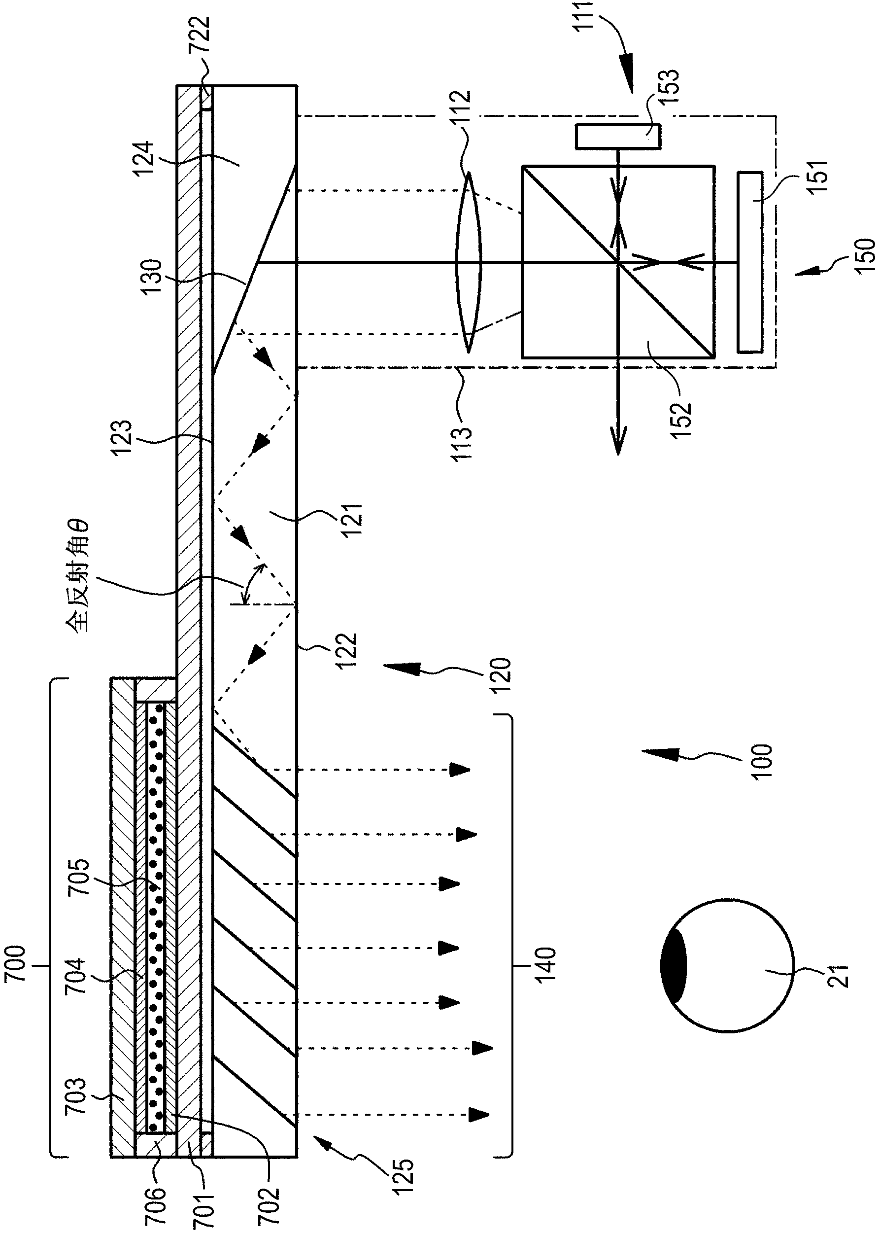
[0211] The third embodiment is a modified example of the first embodiment. Image 6 is a conceptual diagram showing the image display device 300 in the display device (head-mounted display) according to the third embodiment. in addition, Figure 7 is an enlarged cross-sectional view schematically showing a part of a reflective volume hologram diffraction grating. In the third embodiment, in a similar manner to the first embodiment, the image forming apparatus 111 includes the image forming apparatus of the first configuration. In addition, the display device 320 has substantially the same basic configuration or structure as the optical device 120 of the first embodiment except that the first deflecting section and the second deflecting section of different configurations or structures are used.

[0212]In the third embodiment, the first deflecting portion and the second deflecting portion are placed on the front surface of the light guide plate 321 (specifically, the second ...


PUM


Abstract

The invention provides a display apparatus whch includes: a spectacle type frame mounted on a head portion of an observer; and an image display apparatus installed in the frame. The image display apparatus includes an image forming device, and an optical device allowing light output from the image forming device to be incident thereon, to be guided therein, and to be output therefrom. A dimmer which adjusts the amount of external light incident from the outside is disposed in an area of the optical device where the light is output. The dimmer includes a first transparent substrate and a second transparent substrate facing the first substrate, first and second electrodes which are mounted on the first and second substrates, respectively, and an electrolyte sealed between the first and second substrates and containing metal ions. The first electrode includes a conductive material of a fine line shape. The second electrode includes a transparent electrode layer.

Description

technical field [0001] The present disclosure relates to a display device, and more particularly, to a display device using a head mounted display (HMD: head mounted display). Background technique [0002] In recent years, attention has been drawn to augmented reality (AR: augmented reality) technology, which synthesizes and presents virtual objects or various types of information as additional information of a real environment (or a part thereof) as electronic information. To implement such augmented reality technology, for example, head-mounted displays have been studied as devices for presenting visual information. In addition, as an application field, operation support in a real environment is expected. For example, providing technical information to operators who provide or maintain road guidance information. In particular, the head-mounted display is very convenient since the hands are not occupied by the head-mounted display. Also, in a case where the user wants to...

Claims


Application Information

Patent Timeline
Patent Type & Authority Applications(China)
IPC IPC(8): G02B27/01G02B5/32G02B27/44
CPCG02B27/017G02B2027/0118
Inventor 町田晓夫坂本之作桑原美咏子
Owner SONY CORP
Why Eureka
Try Eureka