Input device with luminous pattern

A technology for input devices and luminous patterns, applied in the input/output process of data processing, instruments, and electrical digital data processing, etc., can solve the problems of complex printing process, shorten the service life of backlight input devices, and increase manufacturing costs, so as to avoid Collision wear, improve backlight utilization, reduce the effect of uneven distribution

Inactive Publication Date: 2012-12-19
PRIMAX ELECTRONICS LTD
View PDF4 Cites 4 Cited by
  • Summary
  • Abstract
  • Description
  • Claims
  • Application Information

AI Technical Summary

Problems solved by technology

The screen printing process required to coat the light-shielding substance is more complicated, which increases the manufacturing cost
In addition, the coated light-shielding substance is located on the surface of the mylar sheet 19 or the surface layer 29, which is easy to wear and fall off with time or during transportation, thereby shortening the service life of the backlight input device.

Method used


Image

  • Input device with luminous pattern
  • Input device with luminous pattern
  • Input device with luminous pattern

Examples


Embodiment Construction

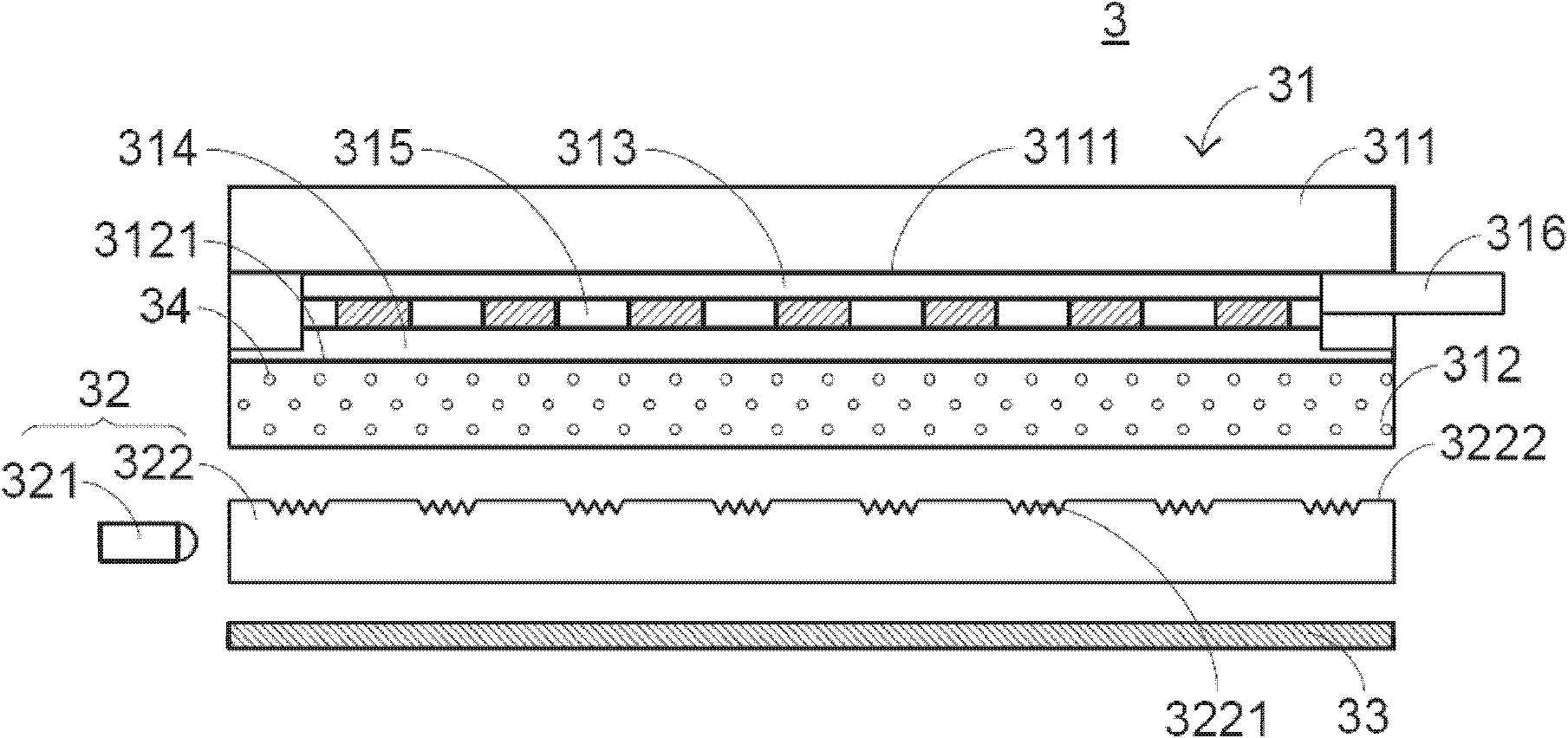
[0032] In view of the defects of the prior art, the present invention provides an input device with a luminous pattern. see image 3, which is a side view of the structure of the input device with light-emitting patterns in the first preferred embodiment of the present invention. The input device 3 with luminous patterns includes an input interface 31 , a backlight module 32 and a black base 33 , and the sequence from top to bottom is the input interface 31 , the backlight module 32 and the black base 33 . The input interface 31 includes a first substrate 311 , a second substrate 312 , a first transparent conductive film 313 , a second transparent conductive film 314 , a micro-dot spacing layer 315 and a connector 316 . The first substrate 311 is located above the second substrate 312 , the first transparent conductive film 313 is disposed on the lower surface 3111 of the first substrate 311 , and the second transparent conductive film 314 is disposed on the upper surface 312...


PUM


Abstract

The invention discloses an input device with a luminous pattern. The input device comprises an input interface and a backlight module. The backlight module comprises a light source and a light guide plate. The light guide plate is provided with a predetermined shading rate and forms at least one pattern at the light guide plate. When the light source is not started, the brightness of the light guide plate is lower than the predetermined shading rate and the pattern is not shown, when the light source is started, the luminous pattern is shown. A substrate of the input interface is formed by uniformly doping multiple shading particles by a transparent plastic material and jetting, and at least one pattern is formed by densely arranging micro light guide structures. According to the invention, the backlight utilization rate is improved, the cost is reduced, a process is simplified, the shading uniformity is improved, the thickness of the input device is reduced, and the long-term collision and abrasion can be avoided.

Description

technical field [0001] The present invention relates to an input device, in particular to an input device with a luminous pattern. Background technique [0002] Touch input devices are widely used. At present, some touch input devices on the market have two different input modes at the same time. The touch input device has a backlight module. When the backlight module is turned on, the touch input device displays a preset pattern to provide a first input mode. When the backlight module is not turned on, no pattern is displayed, thus providing a second input mode. That is to say, the user can determine which input mode the touch input device is currently in according to whether the pattern is displayed, and then input signals according to the mode. For example, when the backlight is not turned on, the appearance of the touch input device is completely black, and the input mode is preset to control the mouse cursor. At this time, the user can move according to the touch inpu...

Claims


Application Information

Patent Timeline
Patent Type & Authority Applications(China)
IPC IPC(8): G06F3/041
Inventor 陈仲渊
Owner PRIMAX ELECTRONICS LTD
Why Eureka
Try Eureka