A power-on buffer control circuit and its control method

A control method and snubber circuit technology, applied in electrical components, output power conversion devices, etc., can solve the problems of power-on snubber circuit resistance damage, low safety and reliability, affecting device life, etc., to avoid overcurrent damage. , Improve safety and reliability, and avoid the effect of snubber resistance damage

Active Publication Date: 2015-09-16
SHENZHEN INVT ELECTRIC
View PDF4 Cites 0 Cited by
  • Summary
  • Abstract
  • Description
  • Claims
  • Application Information

AI Technical Summary

Problems solved by technology

[0003] In the prior art, all frequency conversion equipment includes a power-on buffer circuit, and the frequency conversion equipment generally adopts a common AC-side power-on buffer scheme or a DC-side power-on buffer scheme. However, using the above two power-on buffer circuits for power-on control can only To meet the basic needs of frequency conversion equipment, there are still the following problems:
[0004] 1) The power-on buffer circuit is uncontrollable. After the input terminal of the frequency conversion equipment is powered on, the power-on buffer circuit will work automatically, but this circuit cannot be automatically integrated in the system, and there are certain safety hazards
[0005] 2) During the power-on process of the frequency conversion equipment, if the control signal of the main circuit contactor malfunctions, a large current will flow through the rectifier circuit and the electrolytic capacitor. The current impact will affect the life of the device
[0006] 3) During the operation of the frequency conversion equipment, if the main circuit contactor is disconnected and the subsequent load is not disconnected, it will cause damage to the resistance in the power-on buffer circuit and cause other secondary faults
[0007] Therefore, the power-on buffer circuit in the frequency conversion equipment in the prior art is uncontrollable, has low safety and reliability, and easily causes damage to devices in the frequency conversion equipment

Method used


Image

  • A power-on buffer control circuit and its control method
  • A power-on buffer control circuit and its control method
  • A power-on buffer control circuit and its control method

Examples


Embodiment Construction

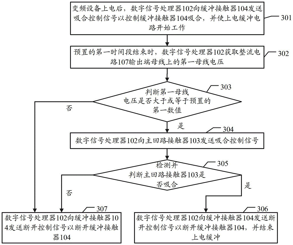
[0043] Embodiments of the present invention provide a power-on buffer control circuit and a control method thereof, which are used to control the power-on buffer process of frequency conversion equipment, have the advantages of high reliability and good safety, and can effectively avoid overcurrent in the rectifier circuit Faults such as damage and snubber resistor damage.

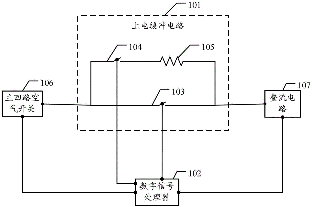
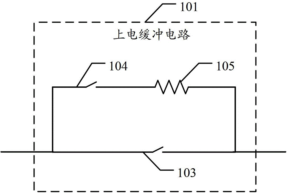
[0044] see figure 1 and figure 2 , figure 1 It is a schematic diagram of the circuit structure of the frequency conversion equipment in the embodiment of the present invention, figure 2 It is a schematic structural diagram of a power-on buffer circuit in an embodiment of the present invention.

[0045] like figure 1 As shown, some circuits of the frequency conversion device in the embodiment of the present invention include: a power-on buffer circuit 101 , a digital signal processor (Digital Signal Processor, DSP) 102 , a main circuit air switch 106 and a rectifier circuit 107 . like figure 2 As s...


PUM


Abstract

An embodiment of the invention discloses a powering buffering control circuit and a control method thereof, and the control method is used for controlling the powering buffering control circuit. The powering buffering control circuit comprises a powering buffering circuit and a digital signal processor, wherein the powering buffering circuit comprises a main loop contactor, a buffering contactor and a buffering resistor. The buffering resistor is connected with the main loop contactor in parallel after being connected with the buffering contactor in series. The digital signal processor is connected with a control coil of the main loop contactor and a control coil of the buffering contactor so as to control connection or disconnection of the main loop contactor and the buffering contactor, so that the powering buffering circuit is controllable, and safety and reliability of the powering buffering circuit are improved.

Description

technical field [0001] The invention relates to the field of frequency conversion equipment, in particular to a power-on buffer circuit and a control method thereof. Background technique [0002] Variable-frequency drive (Variable-frequency Drive, VFD) is a power control device that uses frequency conversion technology and microelectronics technology to control AC motors by changing the frequency of the motor's operating power supply. It can provide the required power supply voltage according to the actual needs of the motor, and then To achieve the purpose of energy saving and speed regulation. In addition, frequency conversion equipment has many protection functions, such as overcurrent, overvoltage, overload protection, etc. With the continuous improvement of industrial automation, frequency converters have been widely used. [0003] In the prior art, all frequency conversion equipment includes a power-on buffer circuit, and the frequency conversion equipment generally ad...

Claims


Application Information

Patent Timeline
Patent Type & Authority Patents(China)
IPC IPC(8): H02M1/36
Inventor 田其金吴建安李炳峰梁敏
Owner SHENZHEN INVT ELECTRIC
Why Eureka
Try Eureka