LED power transmission line with load identification function and load identification method

a technology of power transmission line and function, which is applied in the direction of emergency protective circuit arrangement, emergency protection arrangement for limiting excess voltage/current, electric devices, etc., can solve the problems of manual setting errors, confusion or loss of parameters that have been set for each power output port, and limited maximum output current of led power control apparatus. , to achieve the effect of avoiding over-current damage, reducing errors, and saving user effor

Active Publication Date: 2022-10-27
DELTA ELECTRONICS INC
View PDF1 Cites 0 Cited by
  • Summary
  • Abstract
  • Description
  • Claims
  • Application Information

AI Technical Summary

Benefits of technology

[0008]The main purpose and effect of the present disclosure are to couple the LED power transmission line having the memory apparatus to the control module of the LED power control apparatus and the corresponding LED load so that the control module can acquire the LED specification information, stored in the memory apparatus, corresponding to the LED load. Also, the output current outputted from the power output port is automatically limited according to the LED specification information so as to save the user's effort to manually set the output current parameters by himself, and reduce the risk of errors that may be caused by the manual setting process, thereby avoiding over-current damage caused by non-compliant LED loads that are coupled to the LED power control apparatus through the LED power transmission line.

Problems solved by technology

For example, the maximum output current of the LED power control apparatus is limited to supply power that meets the specifications to the LED loads.
However, if the LED power control apparatus has a plurality of power output ports, the user's process of setting for each power output port is not only cumbersome to manually set, but there may be also a risk of manual setting errors or confusion or loss of the parameters that have been set for each power output port.

Method used


Image

  • LED power transmission line with load identification function and load identification method
  • LED power transmission line with load identification function and load identification method
  • LED power transmission line with load identification function and load identification method

Examples


Embodiment Construction

[0017]Reference will now be made to the drawing figures to describe the present disclosure in detail. It will be understood that the drawing figures and exemplified embodiments of present disclosure are not limited to the details thereof.

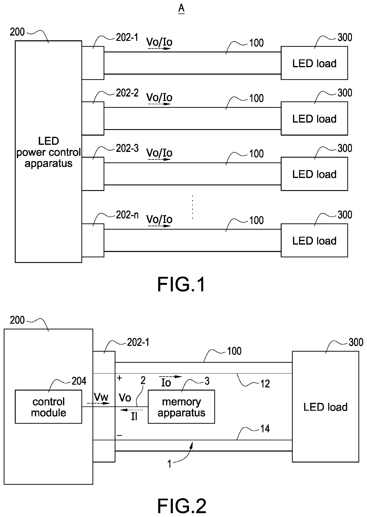
[0018]Please refer to FIG. 1, which shows a block diagram of an LED power supply system according to the present disclosure. The LED power supply system A includes a plurality of LED power transmission lines 100, an LED power control apparatus 200, and a plurality of LED loads 300. The LED power transmission lines 100 are correspondingly coupled to a plurality of power output ports 202-1 to 202-n of the LED power control apparatus 200 and the LED loads 300 so that the LED power control apparatus 200 is coupled to the LED loads 300 through the LED power transmission lines 100. In particular, any one of the LED power transmission lines 100 may be coupled to any one of the power output ports 202-1 to 202-n to transmit an output voltage Vo and output cu...


PUM


Abstract

An LED power transmission line with load identification function is coupled to an LED power control apparatus having a plurality of power output ports and an LED load. The LED power transmission line includes a power transmission circuit, a signal transmission circuit, and a memory apparatus. The power transmission circuit transmits a power outputted from the power output port to the LED load. The signal transmission circuit is coupled to a control module of the LED power apparatus through the power output port. The memory apparatus stores an LED specification information related to an electrical specification of the LED load. The LED specification information is provided to the control module through the signal transmission circuit so that the control module limits an output current outputted from the power output port according to the LED specification information.

Description

BACKGROUNDTechnical Field[0001]The present disclosure relates to an LED power transmission line and a load identification method, and more particularly to an LED power transmission line with load identification function and a load identification method.Description of Related Art[0002]The statements in this section merely provide background information related to the present disclosure and do not necessarily constitute prior art.[0003]In recent years, the development of lighting technology that uses light-emitting diodes (LEDs) as light sources has become increasingly mature, and with the improvement of LED manufacturing process and the increase in production capacity, the manufacturing cost of its hardware has also been reduced year by year. In addition, LED has the advantages of energy saving, long service life and durability, making the application of LED lighting equipment more and more widespread. In contrast, the LED lighting market has an increasing demand for LED power supply...

Claims


Application Information

Patent Timeline
Patent Type & Authority Applications(United States)
IPC IPC(8): H05B45/46H05B47/105
CPCH05B45/46H05B47/105H02H9/02H05B45/3725H05B45/10H05B45/56
Inventor CHIU, JUI-LUNGWENG, CHIA-CHENGCHANG, CHENG-HSUN
Owner DELTA ELECTRONICS INC
Why Eureka
Try Eureka