
A current limiting control circuit and a method applied to an electric machine

A current limiting control, motor drive control technology, applied in the direction of motor control, control system, electrical components, etc., can solve complex problems, achieve the effect of reducing requirements, easy implementation, and increasing service life

Pending Publication Date: 2018-12-21
上海芯北电子科技有限公司
View PDF7 Cites 0 Cited by
  • Summary
  • Abstract
  • Description
  • Claims
  • Application Information

AI Technical Summary

Problems solved by technology

But it requires more complex microcontroller control

Method used


Image

  • A current limiting control circuit and a method applied to an electric machine
  • A current limiting control circuit and a method applied to an electric machine
  • A current limiting control circuit and a method applied to an electric machine

Examples


Embodiment Construction

[0051] In order to more clearly illustrate the embodiments of the present invention or the technical solutions in the prior art, the specific implementation manners of the present invention will be described below with reference to the accompanying drawings. Obviously, the accompanying drawings in the following description are only some embodiments of the present invention, and those skilled in the art can obtain other accompanying drawings based on these drawings and obtain other implementations.

[0052] In order to make the drawing concise, each drawing only schematically shows the parts related to the present invention, and they do not represent the actual structure of the product. In addition, to make the drawings concise and easy to understand, in some drawings, only one of the components having the same structure or function is schematically shown, or only one of them is marked. Herein, "a" not only means "only one", but also means "more than one".

[0053] Embodiment...


PUM


Abstract

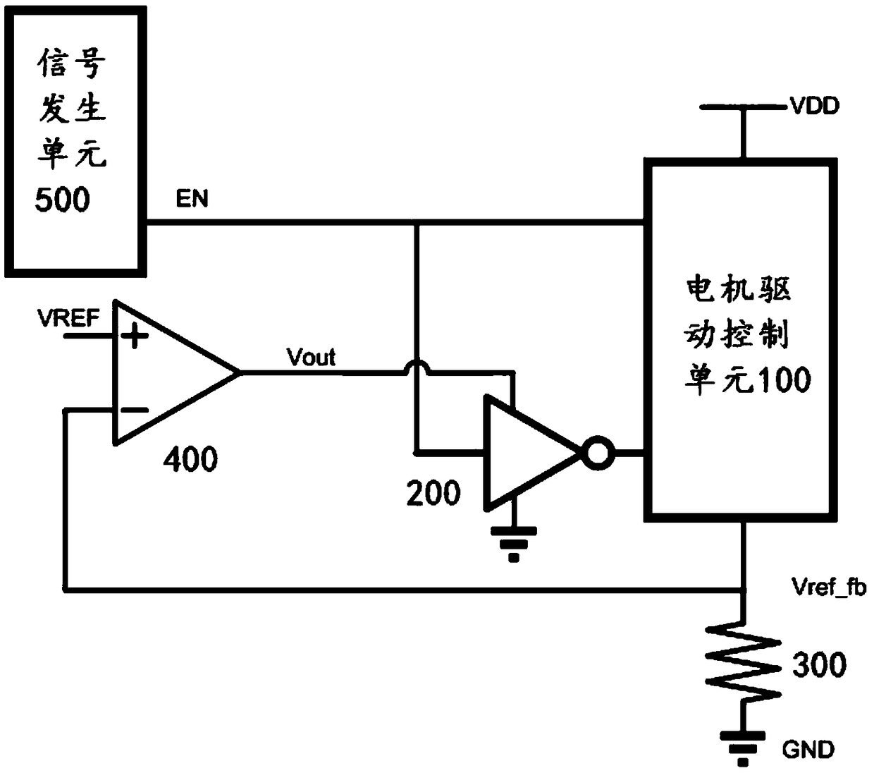
The invention provides a current limiting control circuit and a method applied to a motor. The circuit comprises a motor driving control unit, an inverter, a current inductive resistor, an operationalamplifier and a signal generating unit for generating an enable control signal. The motor driving control unit is respectively connected with a power supply terminal, the signal generating unit and the current inductive resistor; The output end and the input end of the inverter are respectively connected with the motor driving control unit and the signal generating unit. The power supply input terminal of the inverter is connected with the power supply output terminal of the operational amplifier, the non-inverting input terminal of the operational amplifier is connected with a reference voltage, the inverting input terminal of the operational amplifier is respectively connected with the motor driving control unit and the current induction resistor, and the current induction resistor is grounded. The invention realizes the purpose of eliminating the current limiting resistor, simply and conveniently realizing the purpose of limiting the peak current when the motor is powered on, protecting the motor and improving the efficiency.

Description

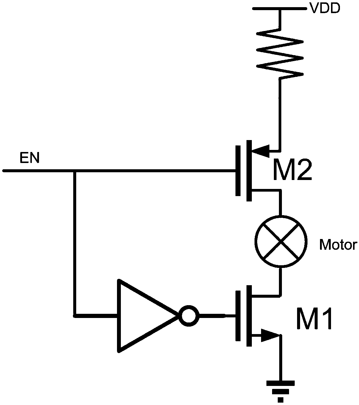
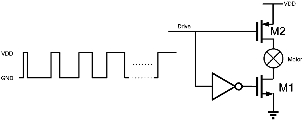
technical field [0001] The invention relates to the field of motor control, in particular to a current limiting control circuit and method applied to motors. Background technique [0002] Motors are widely used in daily life, but designers are troubled by the huge peak current when the motor is powered on. Because the motor does not start to rotate within a short period of time when the motor is powered on, the entire coil is connected to the power supply at this time, and the peak current is close to V / R. V is the driving voltage of the motor, and R is the internal resistance of the motor coil. Generally, the internal resistance of the motor coil is only a few ohms, so the peak current generated can reach more than 1 ampere. Such a large peak current not only makes board-level circuits difficult to implement, but also requires extremely high driving capability of the front-end power supply. Moreover, directly driving the motor for a long time will greatly reduce the life...

Claims


Application Information

Patent Timeline
Patent Type & Authority Applications(China)
IPC IPC(8): H02P29/024
CPCH02P29/027
Inventor 黄硕荀本鹏
Owner 上海芯北电子科技有限公司
Learn More