Electric cooking device and electromagnetic heating system for electric cooking device

A technology of cooking equipment and heating system, applied in the fields of electromagnetic heating system and electric cooking equipment, can solve the problems of current monitoring and protection of switching tube, sudden change of resonant capacitor voltage, and easy damage of switching tube, so as to avoid overcurrent damage and improve reliability. sexual effect

Active Publication Date: 2022-02-25
FOSHAN SHUNDE MIDEA ELECTRICAL HEATING APPLIANCES MFG CO LTD
View PDF7 Cites 0 Cited by
  • Summary
  • Abstract
  • Description
  • Claims
  • Application Information

AI Technical Summary

Problems solved by technology

The average value of the current here is calculated according to the frequency of the input alternating current of 50Hz. However, the operating frequency of the electromagnetic heating system during induction heating is about 20~40kHz, and the maximum instantaneous current of the switching tube in a single cycle can reach 40-50A. In addition, if the voltage of the collector of the switch tube is higher than zero volts before it is turned on, it is necessary to force the resonant capacitor in the electromagnetic heating system to be charged. Due to the on-off of the switch tube, the voltage of the resonant capacitor will change suddenly. Therefore, the switch At the moment when the tube is turned on, there will be a transient impact current of more than 60A flowing through the switch tube.
[0003] It is precisely because of the existence of the above-mentioned inrush current that the electromagnetic heating system in the related art does not monitor and protect the current of each working cycle of the switch tube, so that the switch tube is easily damaged, which in turn leads to poor reliability of the electromagnetic heating system

Method used


Image

  • Electric cooking device and electromagnetic heating system for electric cooking device
  • Electric cooking device and electromagnetic heating system for electric cooking device
  • Electric cooking device and electromagnetic heating system for electric cooking device

Examples


Embodiment Construction

[0023] Embodiments of the present invention will be described in detail below, and examples of the embodiments are illustrated in the drawings, in which the same or similar reference numerals represent the same or similar elements or elements having the same or similar functions. The following is exemplary, and is intended to be utilized to illustrate the invention.

[0024] The electromagnetic heating system and the electromagnetic heating system of the electrically cooking apparatus for electrically cooking apparatus are described below with reference to the accompanying drawings.

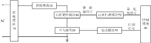
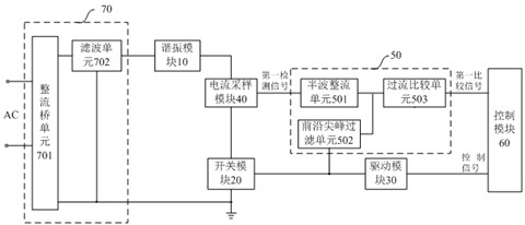
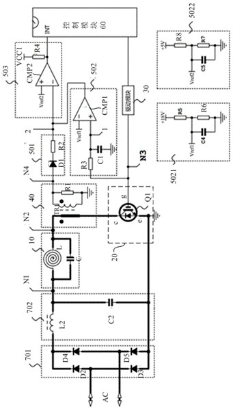
[0025] figure 1 A block diagram of an electromagnetic heating system for a electrically cooking apparatus according to an embodiment of the present invention. Among them, if figure 1 As shown, the electromagnetic heating system can include: resonance module 10, switch module 20, drive module 30, current sampling module 40, overcurrent detection module 50, control module 60.

[0026] The switch modul...


PUM


Abstract

The invention discloses an electric cooking device and an electromagnetic heating system used for the electric cooking device, wherein the electromagnetic heating system includes: a resonance module; a switch module; a drive module; a current sampling module, which is used to collect the current flowing into the switch module, and Generate the first detection signal according to the current; the overcurrent detection module filters out the inrush current in the first detection signal when the switch module is turned on, and outputs the first comparison signal according to the first detection signal; the control module is used to output the driving signal to the driving module, so as to drive the switching module on / off through the driving module, and stop outputting the driving signal when judging the overcurrent of the switching module according to the first comparison signal, so as to turn off the switching module. The system can monitor the current flowing through the switch module, and turn off the switch module when the switch module is overcurrent, so as to protect the switch module from overcurrent, and can filter the inrush current when the switch module is turned on, so as to prevent the inrush current Trigger false protection.

Description

Technical field [0001] The present invention relates to the field of electrical techniques, and Background technique [0002] Electric cooking artifacts, electric cooking, electric rice cooker, electric pressure cooker, etc. Take 10A. The current here is calculated according to the frequency of 50 Hz, however, the electromagnetic heating system induces the operating frequency of about 20 to 40 kHz, and the maximum instantaneous current of the switch tube in a single cycle can reach 40-50A. Further, if the voltage of the collector electrode is higher than zero volts before the switch is turned on, it is necessary to force a resonant capacitor to charge in an electromagnetic heating system. Since the switch of the switching tube, the voltage mutation of the resonant capacitance, therefore, the switch The moment of tube is turned on, there will be more than 60A transient impact current flow through the switch tube. [0003] It is because of the presence of the impact current describ...

Claims


Application Information

Patent Timeline
Patent Type & Authority Patents(China)
IPC IPC(8): H05B6/06H05B6/12
CPCH05B6/06H05B6/12H05B2206/02
Inventor 曾露添江德勇刘文华黄庶锋张帆雷俊王云峰邢凤雷
Owner FOSHAN SHUNDE MIDEA ELECTRICAL HEATING APPLIANCES MFG CO LTD
Why Eureka
Try Eureka