Control circuit and transformation system for power converter and control method of transformation system

A technology of conversion system and control circuit, which is applied in the field of conversion system and can solve problems such as large on-state loss

Active Publication Date: 2012-12-19
DELTA ELECTRONICS INC
View PDF2 Cites 8 Cited by
  • Summary
  • Abstract
  • Description
  • Claims
  • Application Information

AI Technical Summary

Problems solved by technology

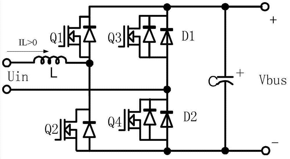
It can be seen from the above working process that although the traditional PFC circuit has low on-state loss and small common-mode interference, the body diode of the first MOSFET or the body diode of the second MOSFET in the first bridge arm is always on in the stage of inductive energy release. state, so the on-state loss is still large

Method used


Image

  • Control circuit and transformation system for power converter and control method of transformation system
  • Control circuit and transformation system for power converter and control method of transformation system
  • Control circuit and transformation system for power converter and control method of transformation system

Examples


Embodiment Construction

[0068] In order to make the technical content disclosed in this application more detailed and complete, reference may be made to the drawings and the following various specific embodiments of the present invention, and the same symbols in the drawings represent the same or similar components. However, those skilled in the art should understand that the examples provided below are not intended to limit the scope of the present invention. In addition, the drawings are only for schematic illustration and are not drawn according to their original scale.

[0069]In the detailed description and claims of this application, the description of "coupled with" can generally refer to a component that is indirectly connected to another component through other components, or a component that does not need to be transparent. directly connected to another component through another component.

[0070] In the detailed description and claims of this application, unless the article is specifical...


PUM


Abstract

The invention provides a control circuit and a transformation system for a power converter and a control method of the transformation system. The transformation system comprises an alternating-current power source, the power converter and the control circuit. A first bridge arm of the power converter comprises a first switch tube and a second switch tube which are connected in series, a second end of the first switch tube is connected with a first end of the second switch tube and is coupled to a first end of the alternating-current power source via an inductance component, and the first switch tube and the second switch tube work at the first switch frequency. A second bridge arm of the power converter is connected with the first bridge arm in parallel. The control circuit is used for controlling the first switch tube and the second switch tube, so that current flowing through the inductance component is reduced to zero before finishing time of at least one of the first switch period. By controlling the first switch tube and the second switch tube in the first bridge arm, the current flowing through the inductance component is reduced to zero before the finishing time of at least one of the first switch period, and accordingly, on-state loss of the power converter can be reduced since the power converter can work in the DCM (direct current main) mode within part of first switch periods, and work efficiency is improved.

Description

technical field [0001] The invention relates to the technical field of power electronics, in particular to a control circuit for a power converter, a conversion system and a control method for the conversion system. Background technique [0002] At present, in order to reduce the severe harmonic pollution caused by the frequent use of power electronic devices to the power grid, it is usually necessary to introduce a power factor correction (PFC) circuit, and the input current harmonics meet the preset harmonic requirements through the PFC circuit. In addition, the development trend of the PFC circuit, like most power supply products, is developing in the direction of high efficiency and high power density. [0003] Taking the bridgeless PFC circuit topology as an example, this circuit has many advantages such as low on-state loss, low common-mode interference, and high utilization of components. For example, a bridgeless PFC circuit includes a first bridge arm and a second ...

Claims


Application Information

Patent Timeline
Patent Type & Authority Applications(China)
IPC IPC(8): H02M5/293
CPCY02B70/1491H02M2003/1586H02M7/217H02M2001/0054H02M2007/2195Y02B70/126H02M1/4233H02M1/4225H02M1/4241Y02B70/10H02M1/0054H02M3/1586
Inventor 言超王晓媛叶益青
Owner DELTA ELECTRONICS INC
Why Eureka
Try Eureka